Quadruped Part 2 - Hardware
Continuing where I left off last blog post, I now had suitable motor candidates and working motor controllers. Because my mill has been down since I finished my wheeled biped (haven’t gotten around to finishing the new mill controller because of Battlebots) I decided it was fine to outsource the parts for this quadruped build in the mean time.
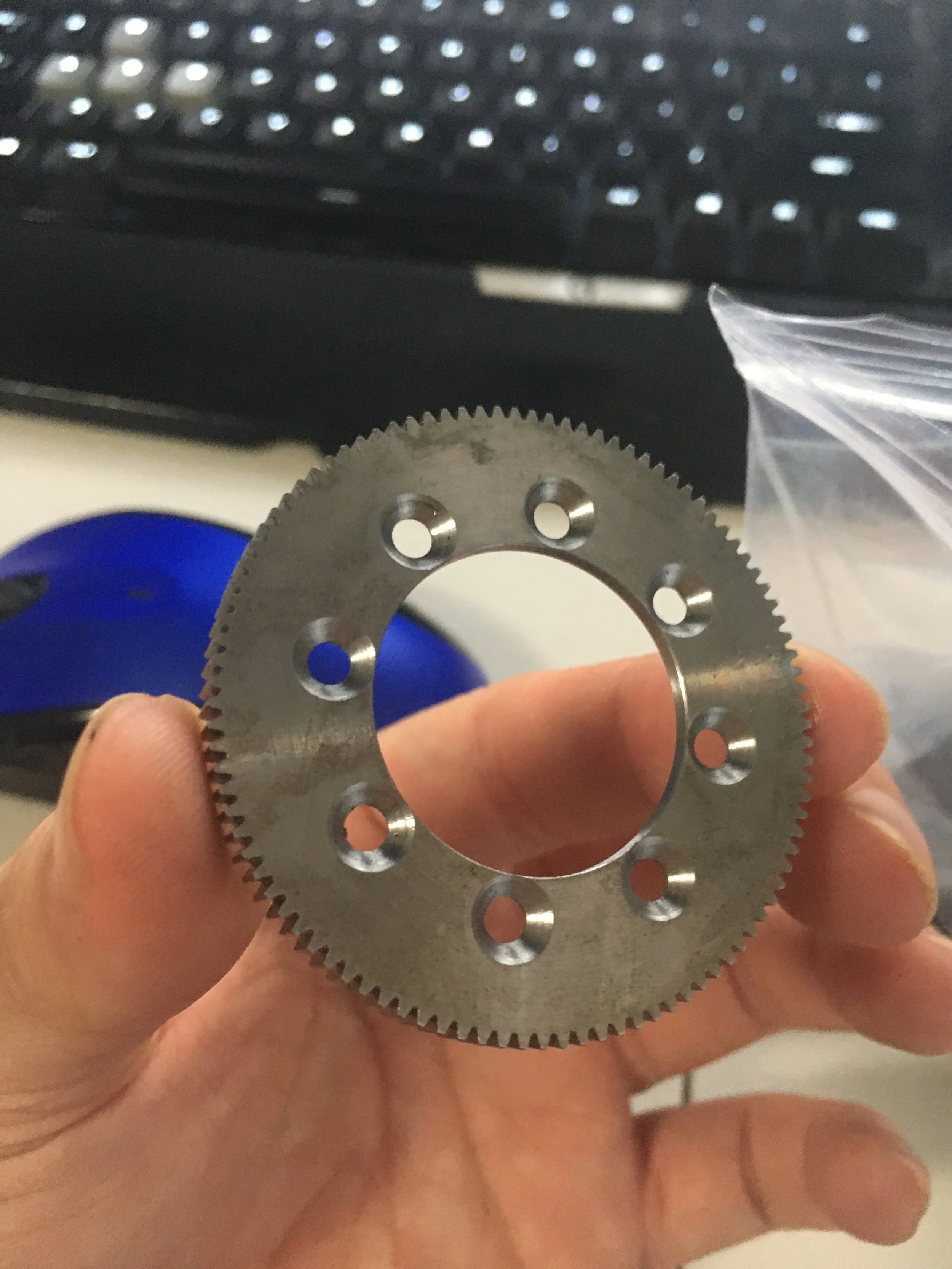
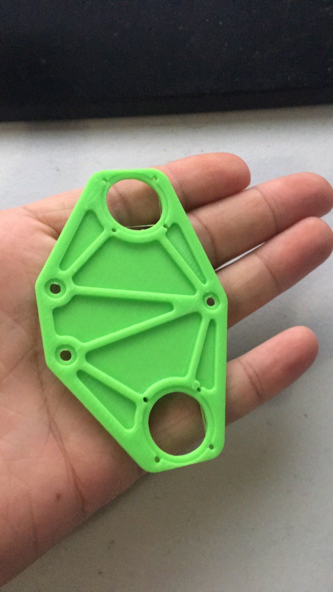
To start off with I ordered the spur gears for the main reductions. There’s a 4:1 spur gear reduction for all 3 leg joints, and then an additional 2:1 belt reduction to the knee.
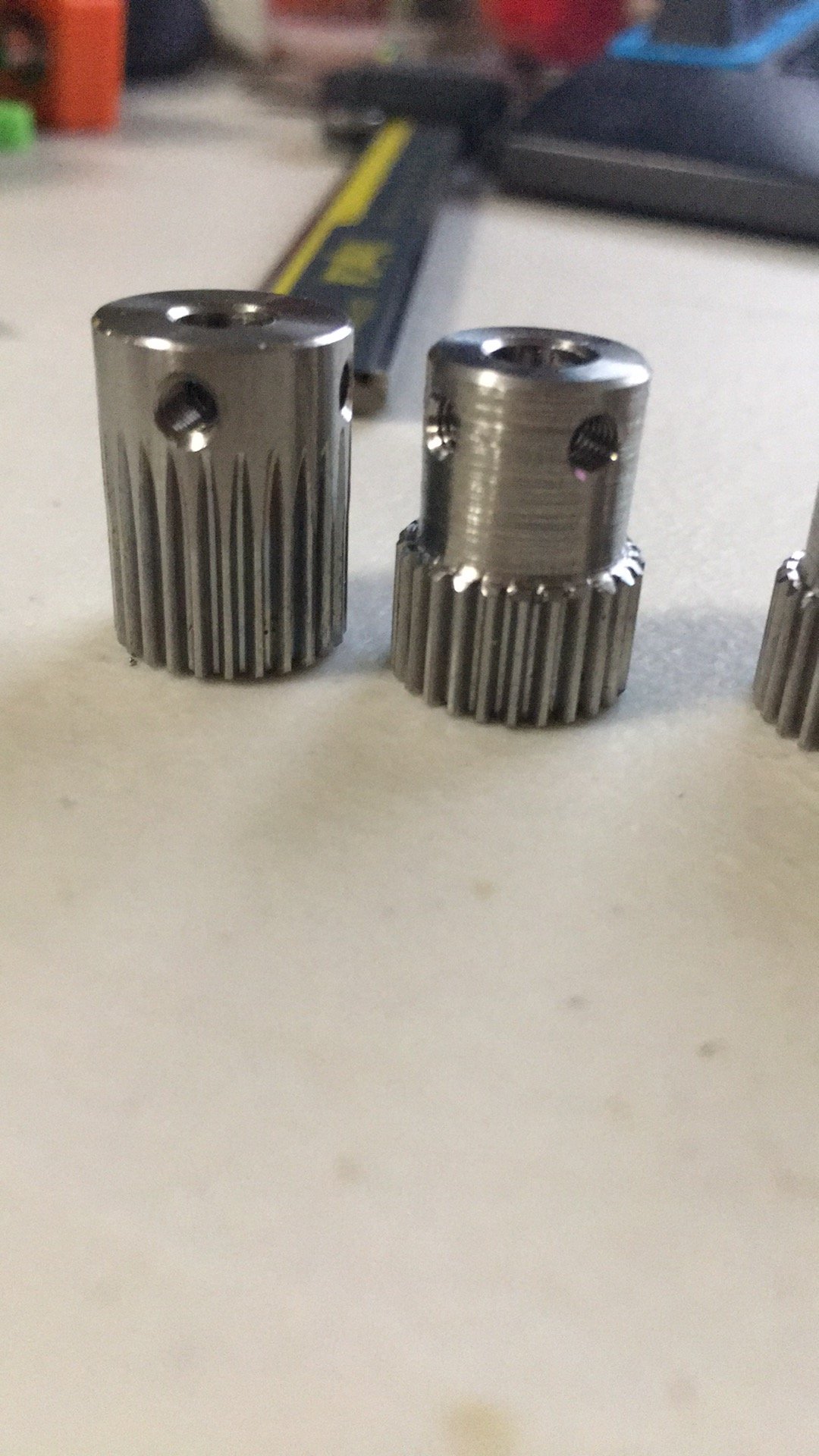
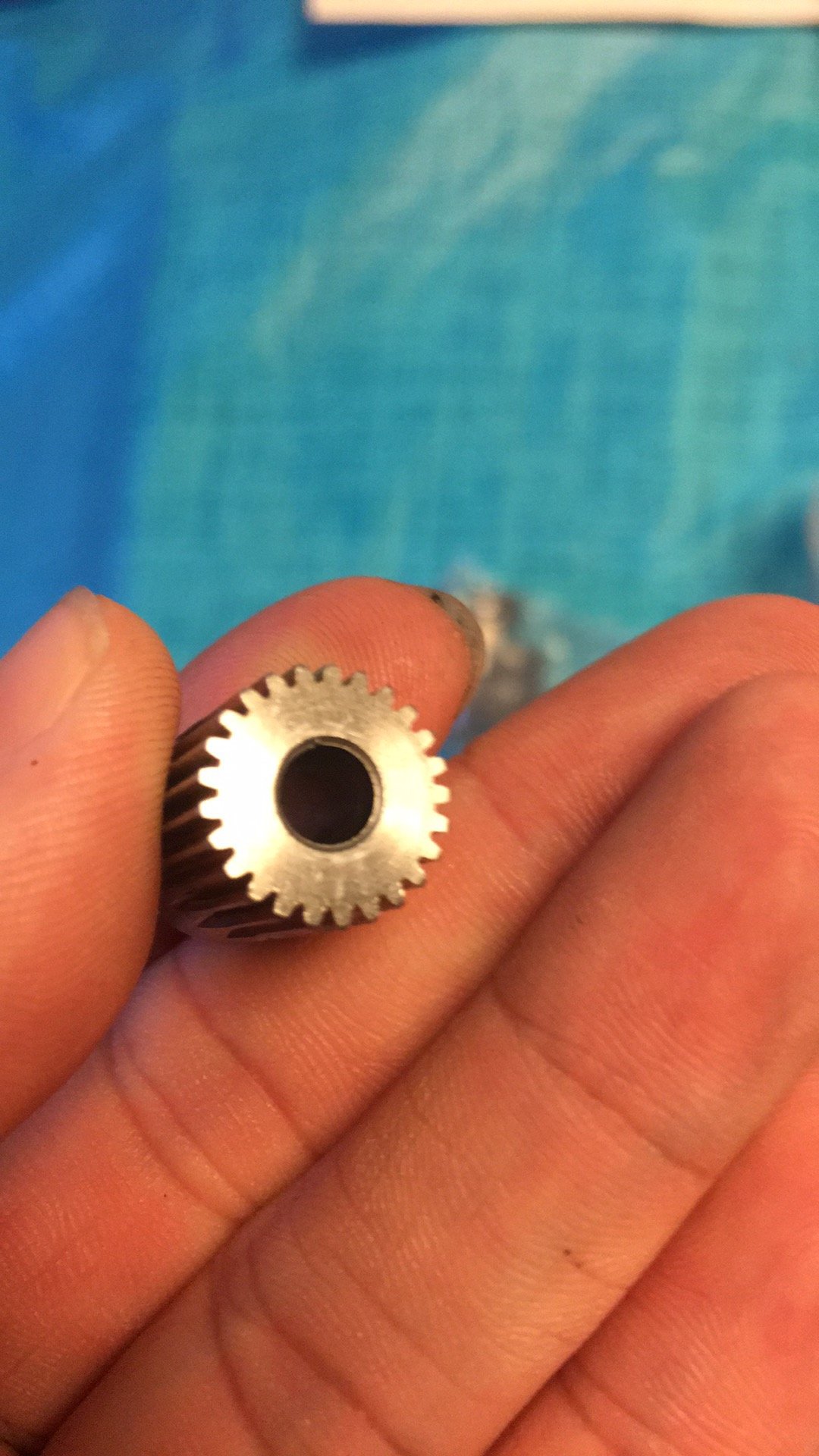
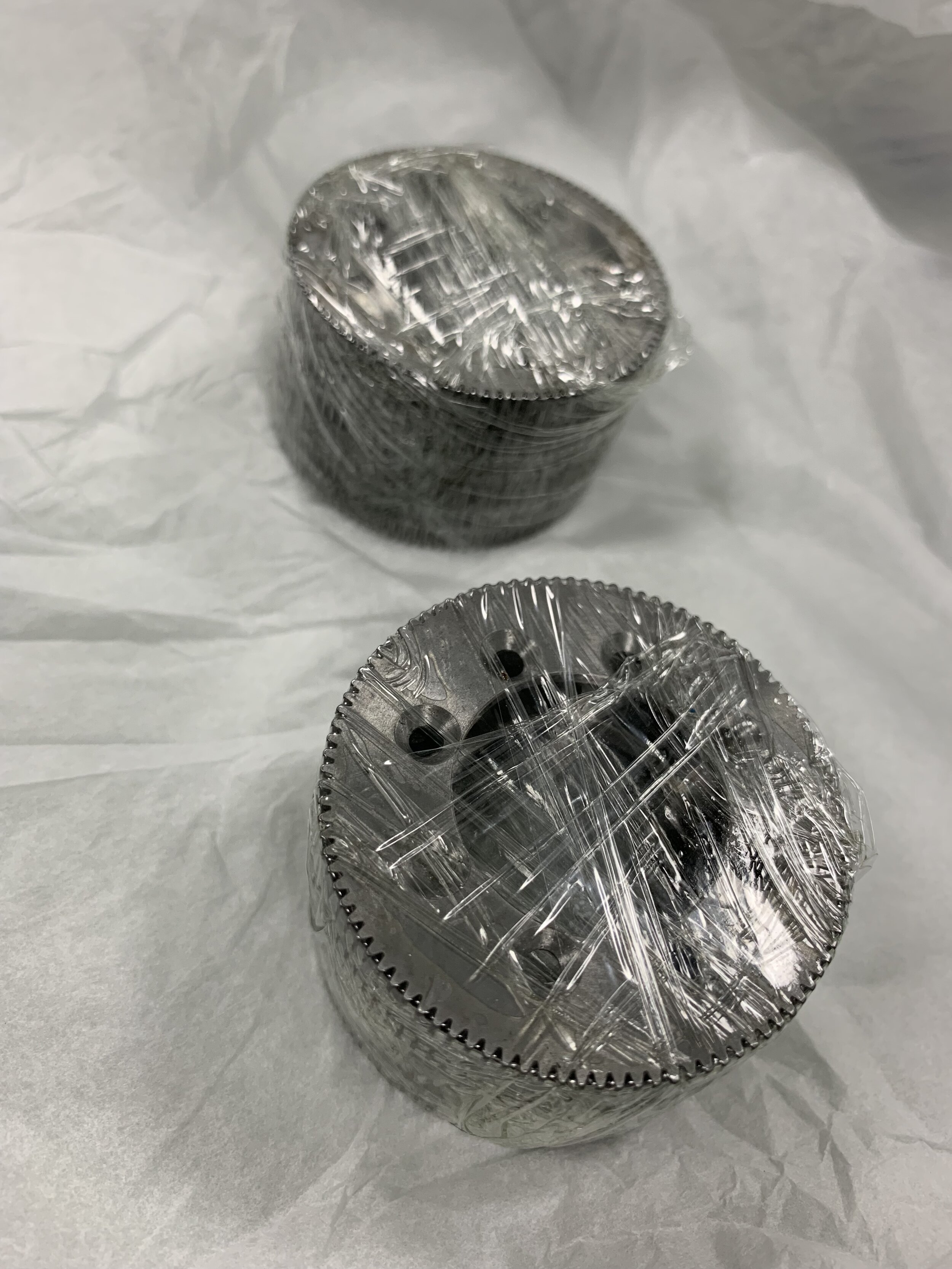
The gears are Mod 0.5. I tried finding COTS decent spur gears and although the RC car ones were close in terms of usable mounting patterns and lightening, I ended up ordering custom ones so I could control the quality. I used stock pinions which I turned down the shank on my lathe.
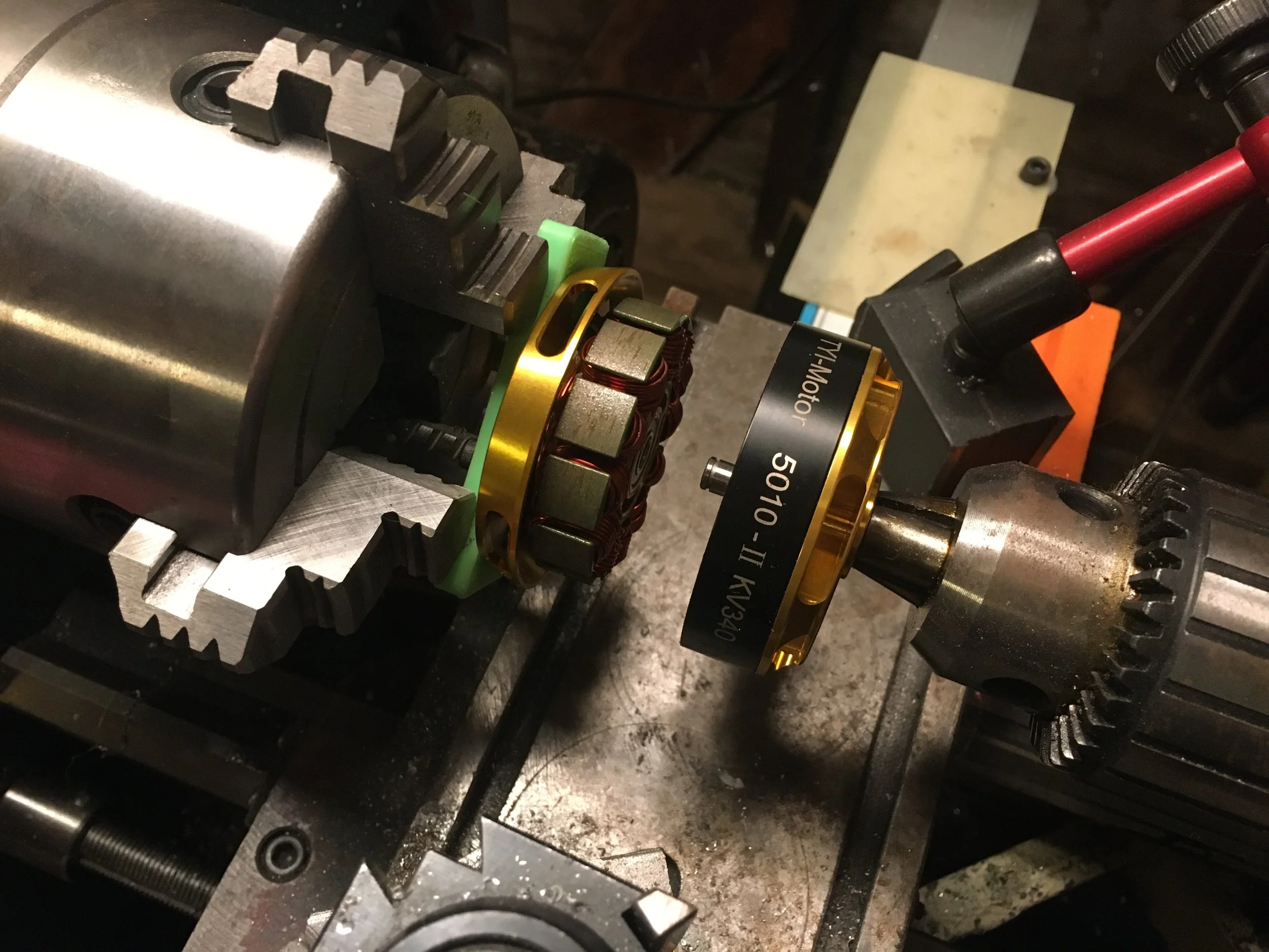
The motors all needed custom shafts which I ordered for quite cheap from Misumi. The hard part was disassembling the motors so I made a jig and used my lathe for not lathe things.
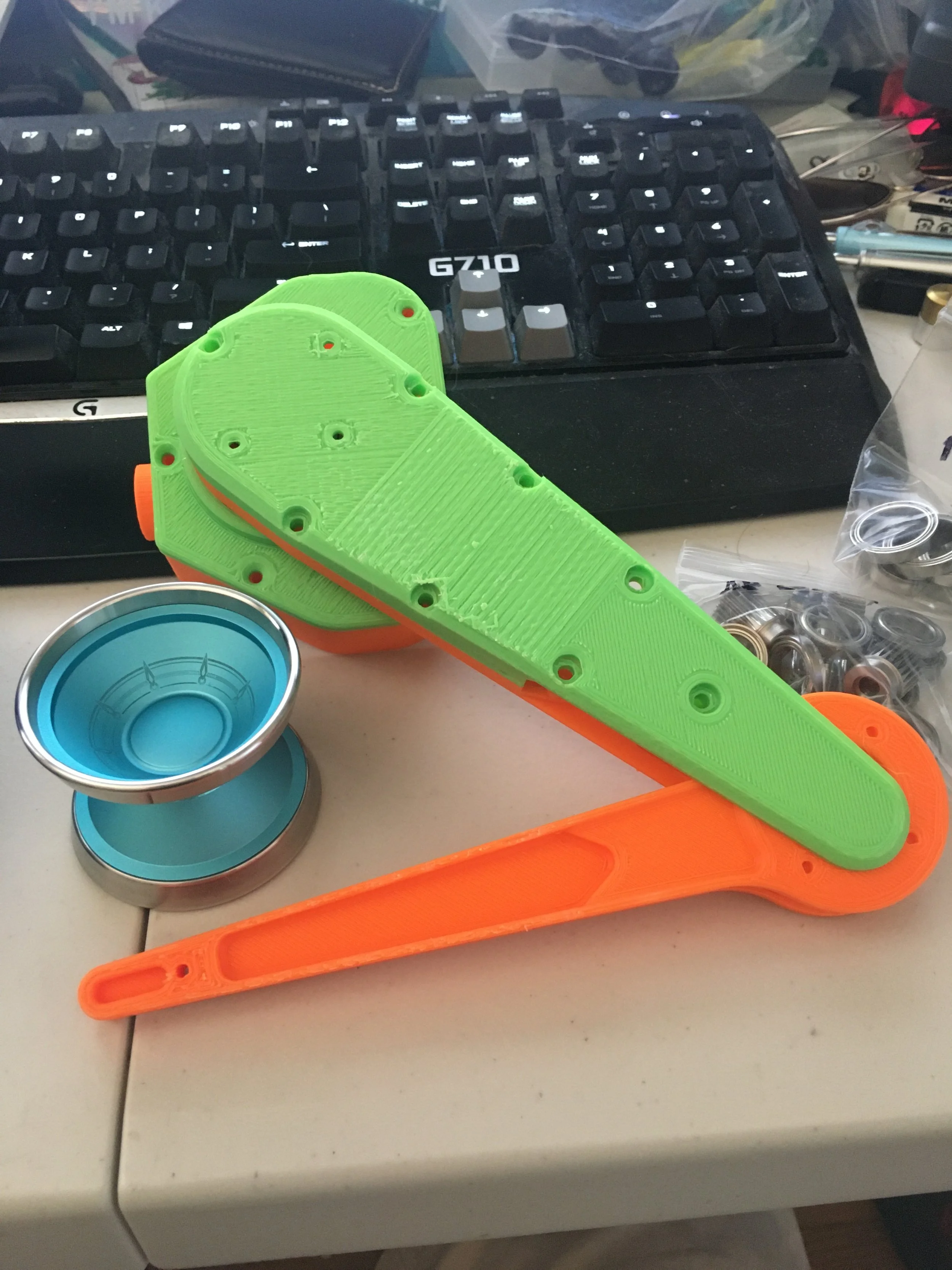
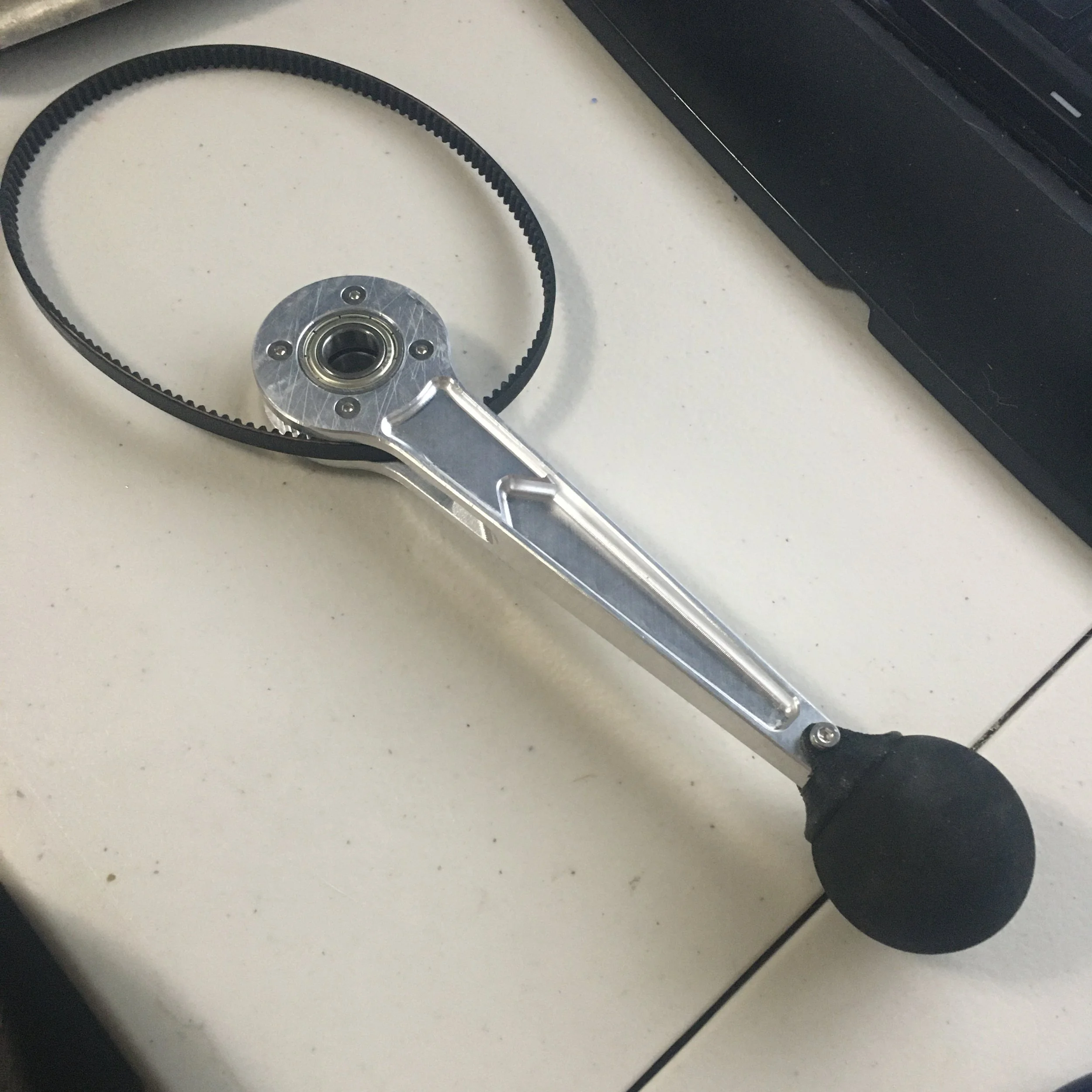
With the motors ready I printed the remainder of the leg parts for a test fit.
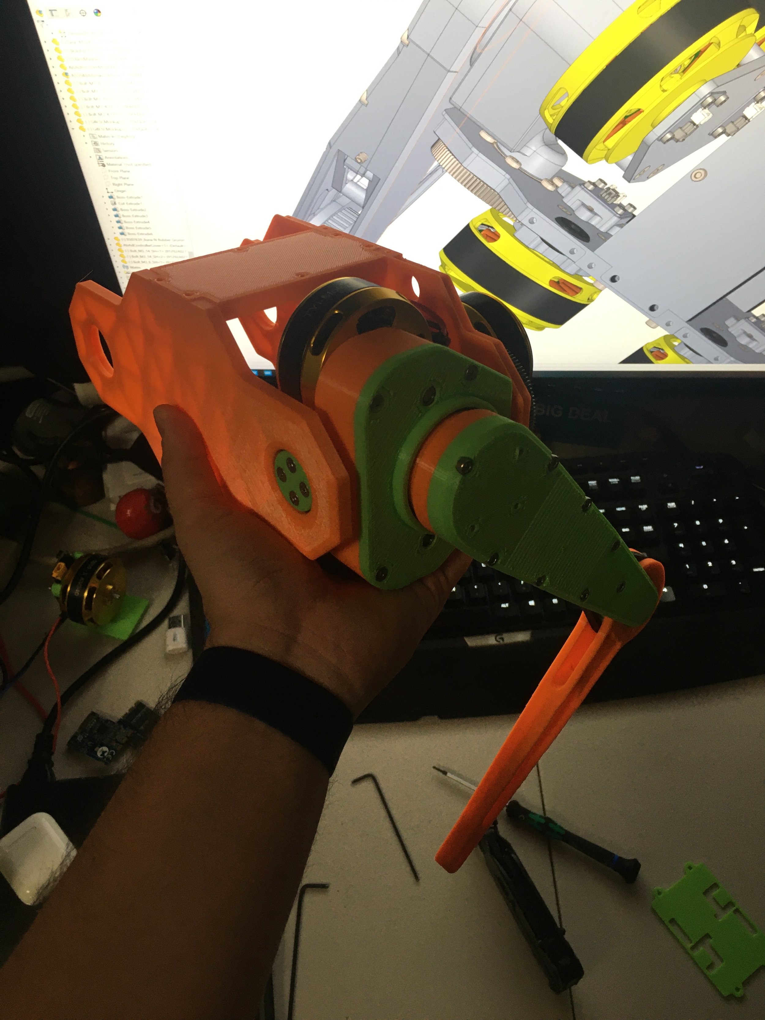
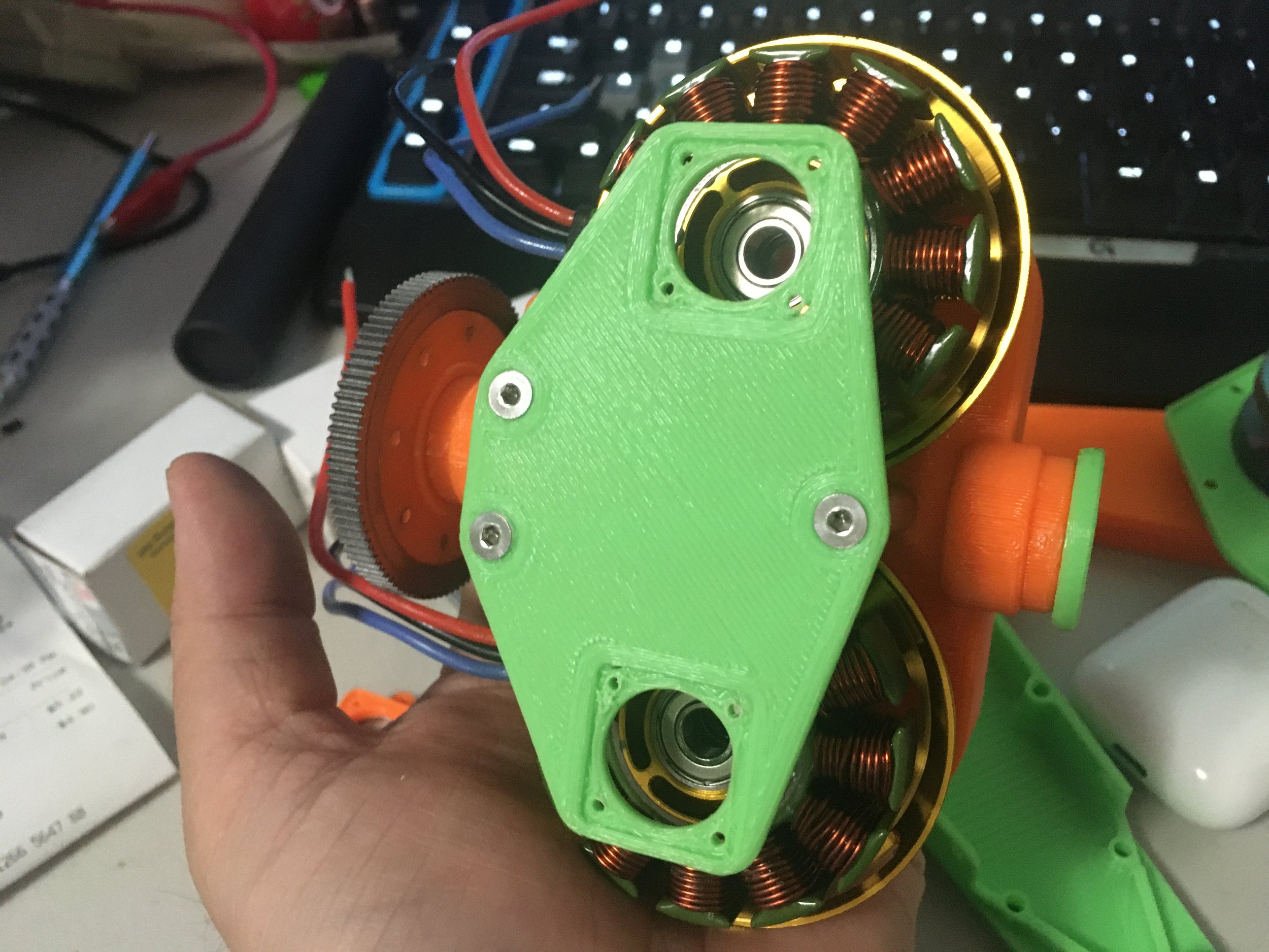
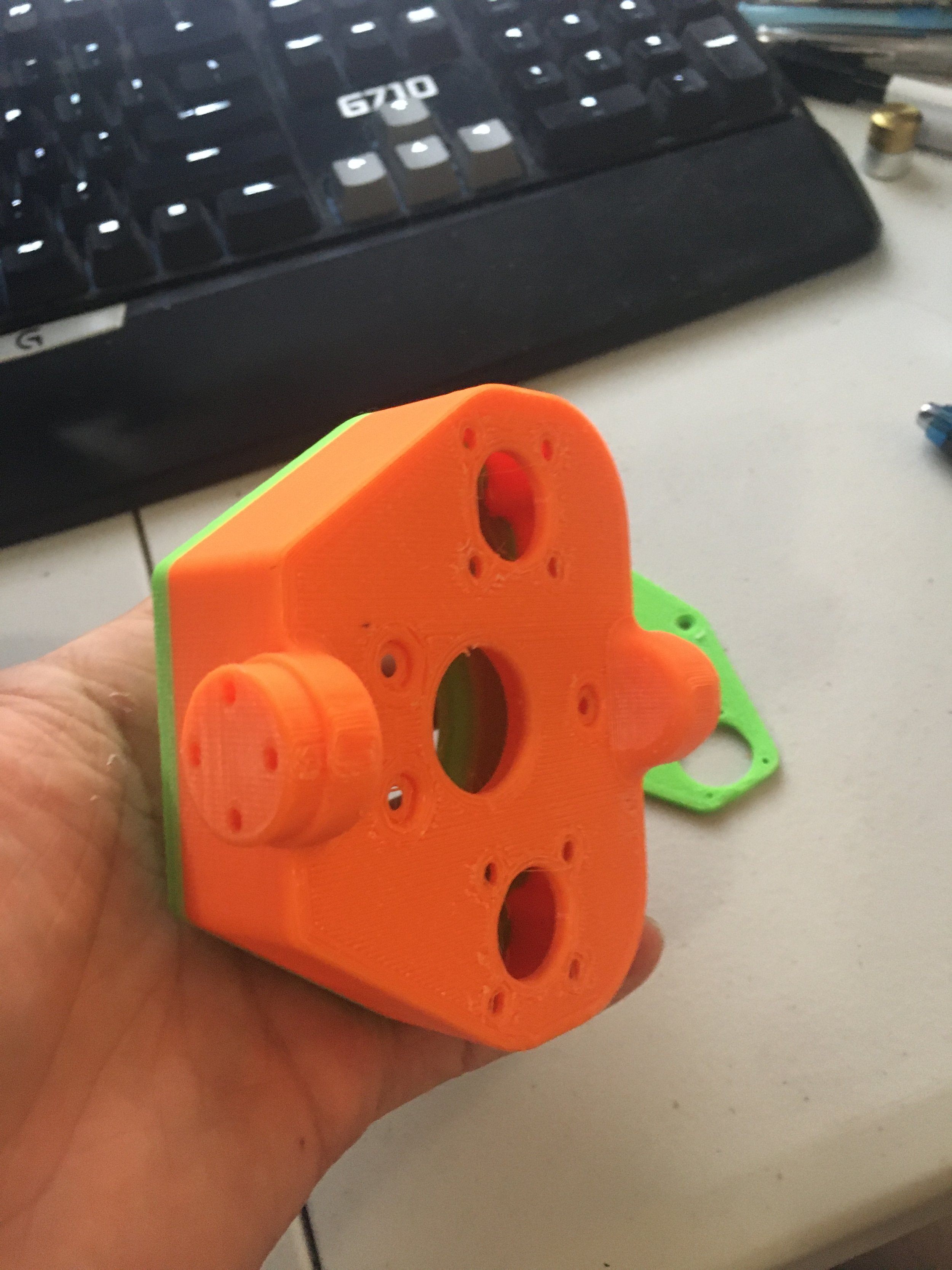
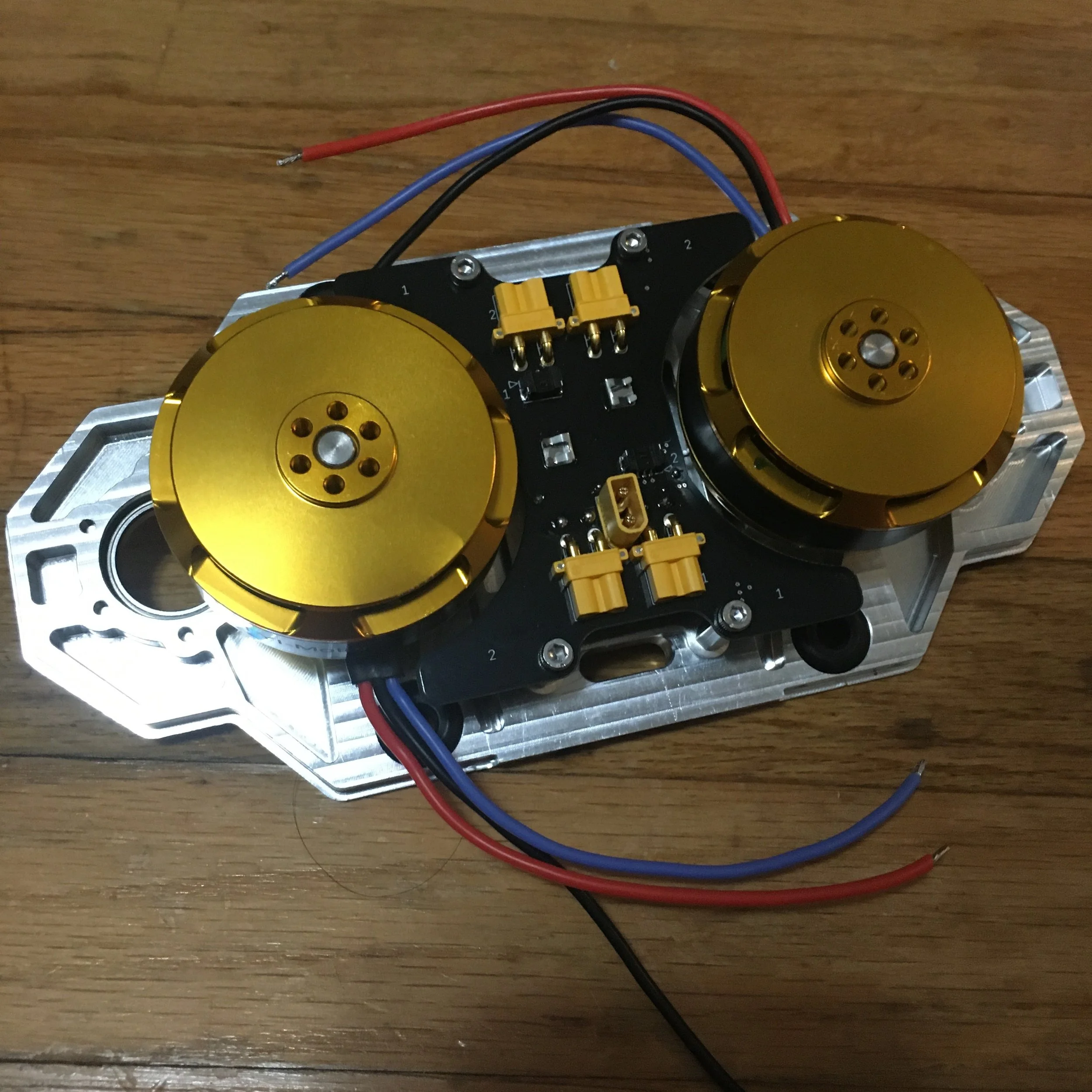
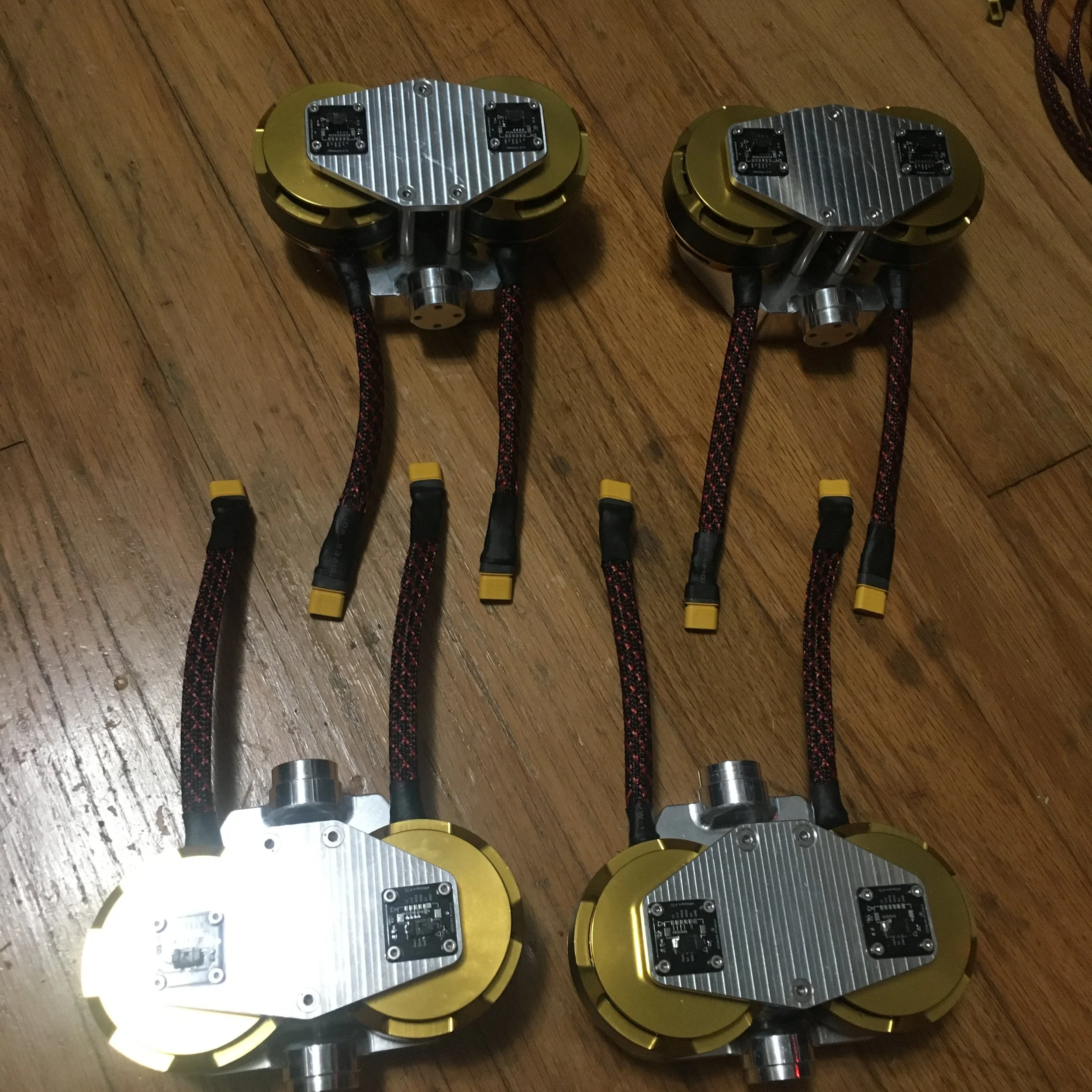
Now is probably a good time to talk about the design a bit. First, I thought it would be interesting to use the coaxial shaft drive method (like on swerve drives) because this allows continuous rotation of the entire leg. This also keeps the leg inertia lower. The motors were placed above and below each other to reduce overall length of the robot because the abad joint is not used as much and can deal with the increase in inertia. The belt drive to the knee serves two purposes; first obviously it keeps the leg inertia low because the motor is far away but it also provides more torque to the knee which we saw could be beneficial from experience with Mini Cheetah. The belts are tensioned using some of the many leftover belt tensioners from my wheeled biped.
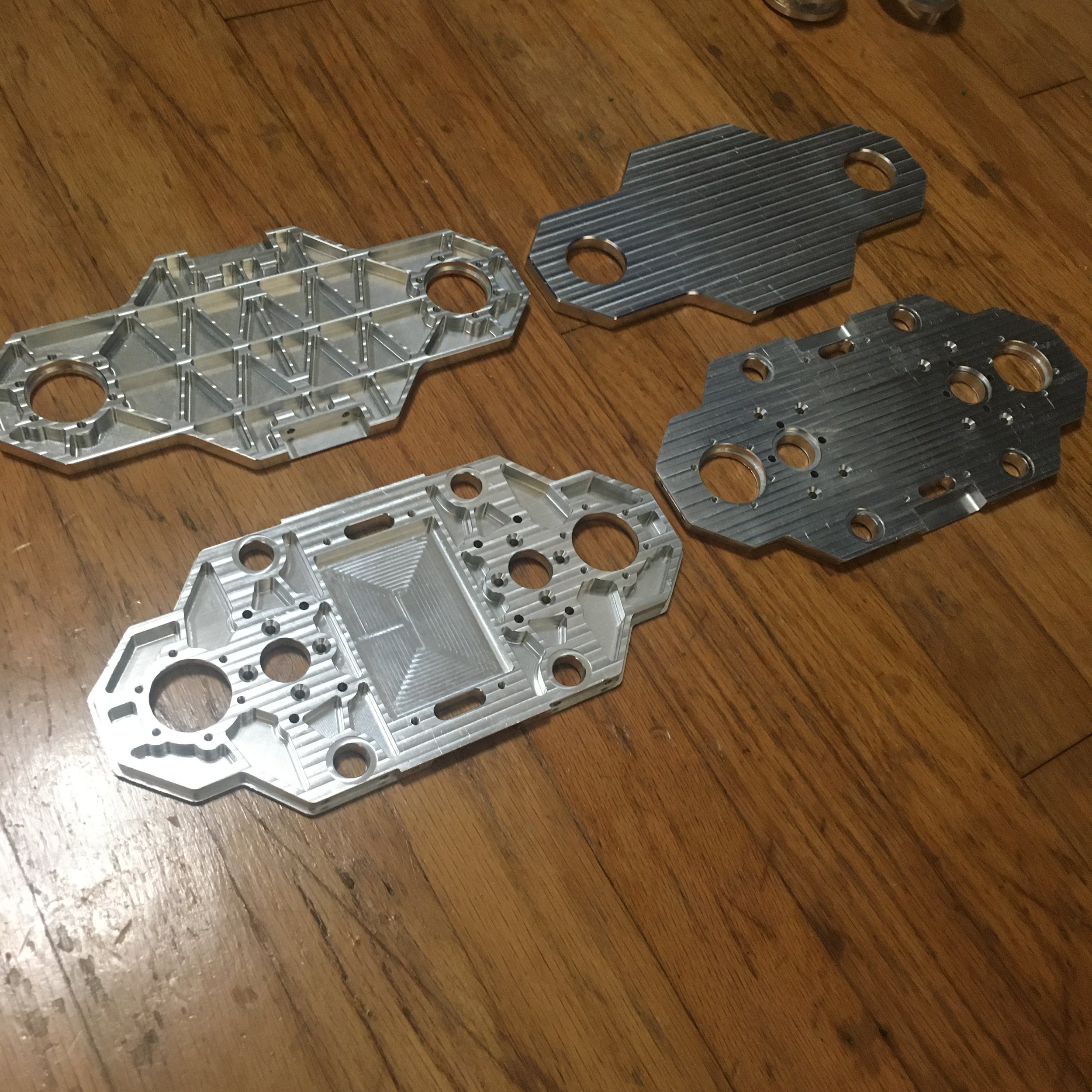
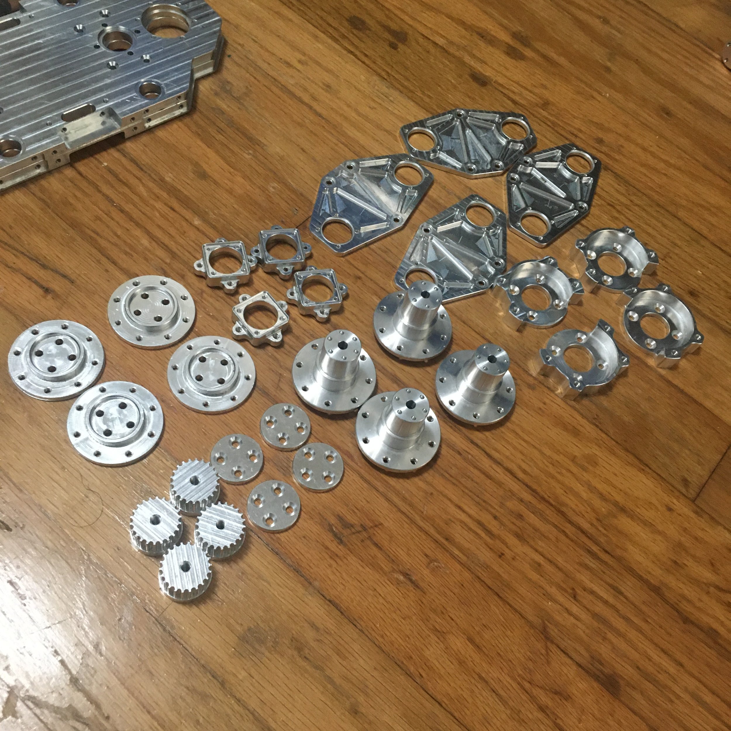
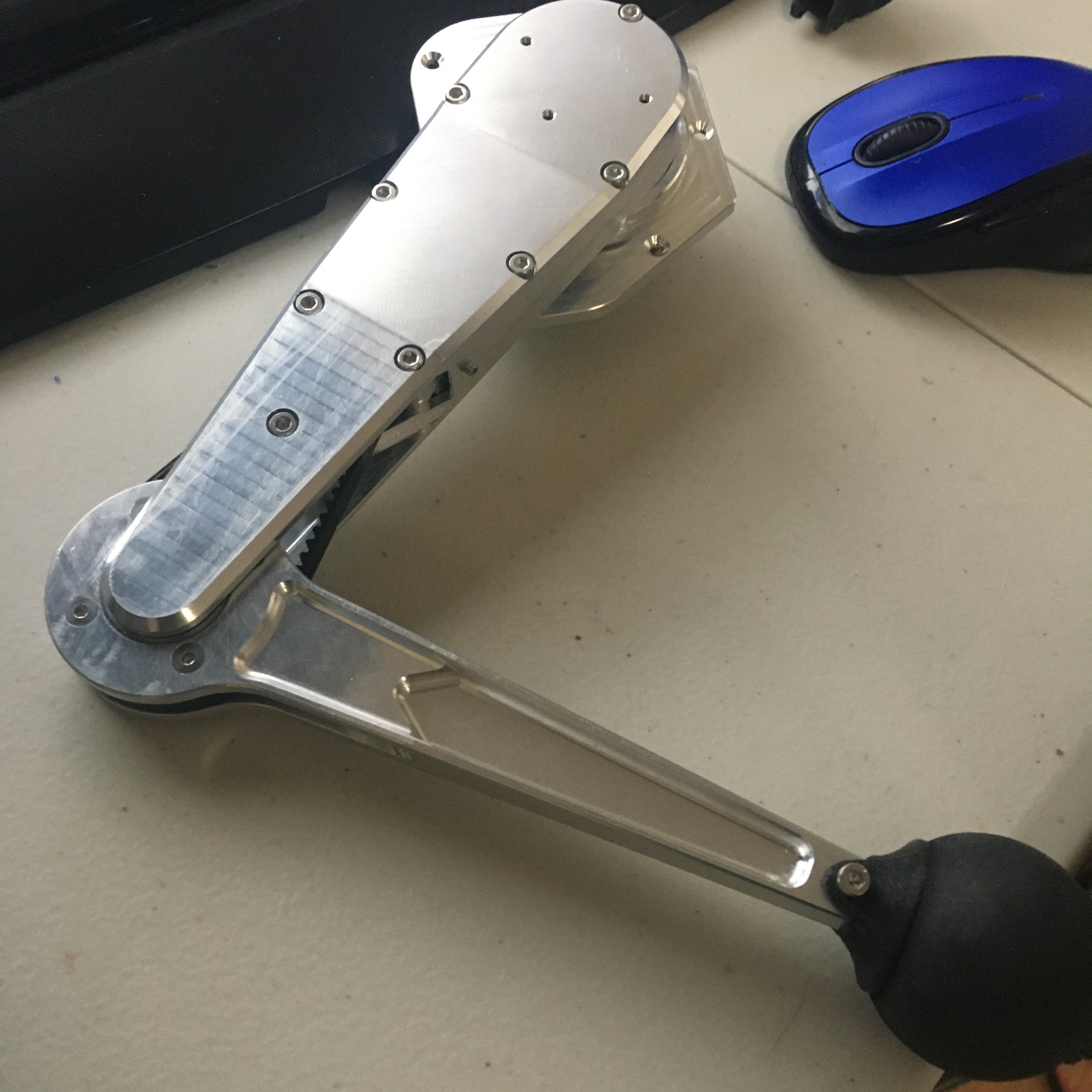
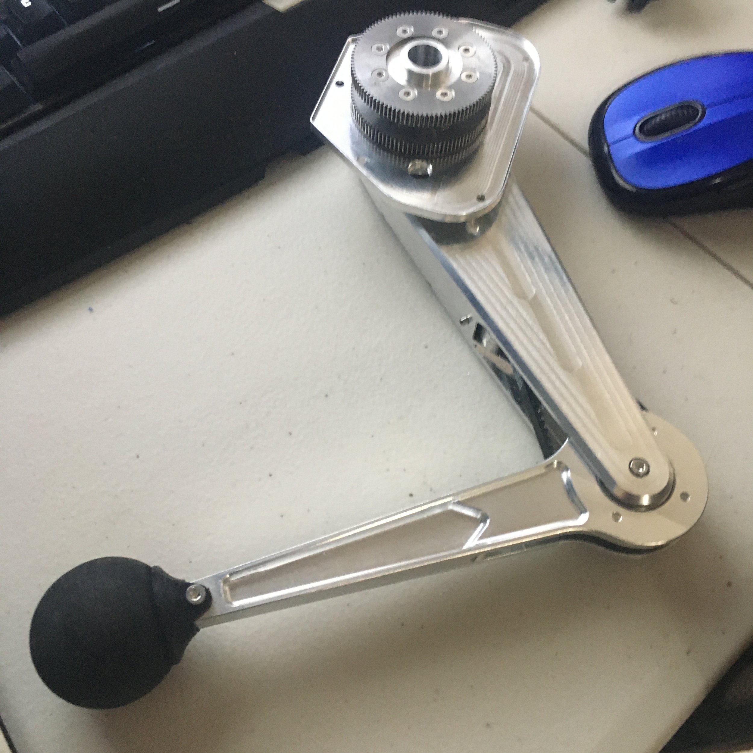
After seeing that the printed parts all worked together well, I placed an order for all the CNC’d parts from China.
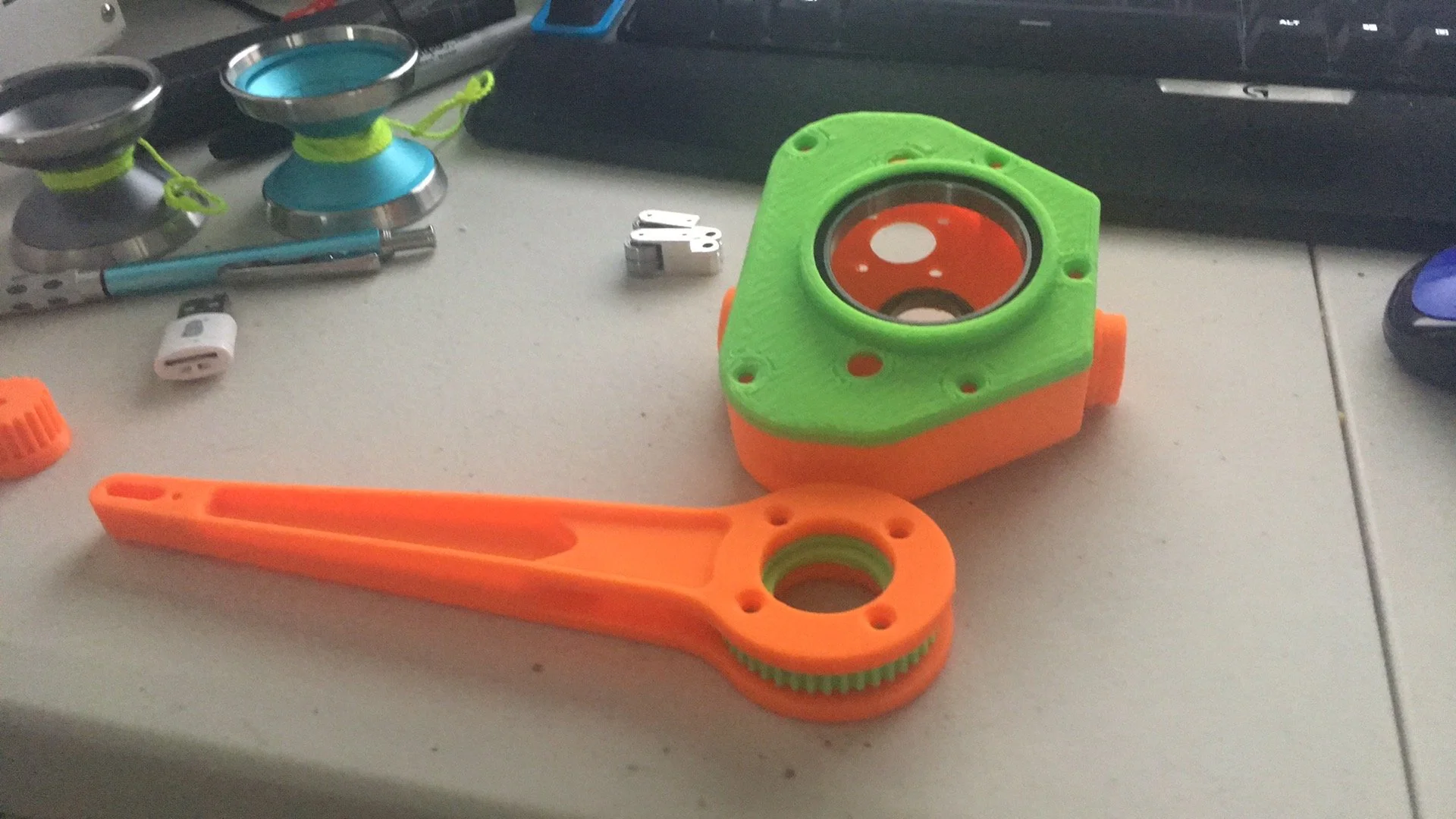
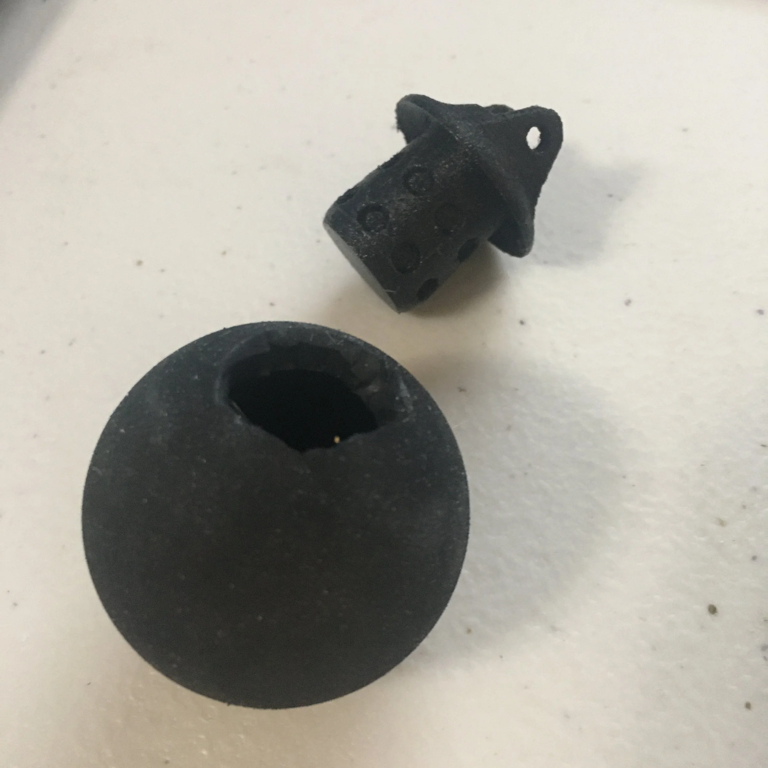
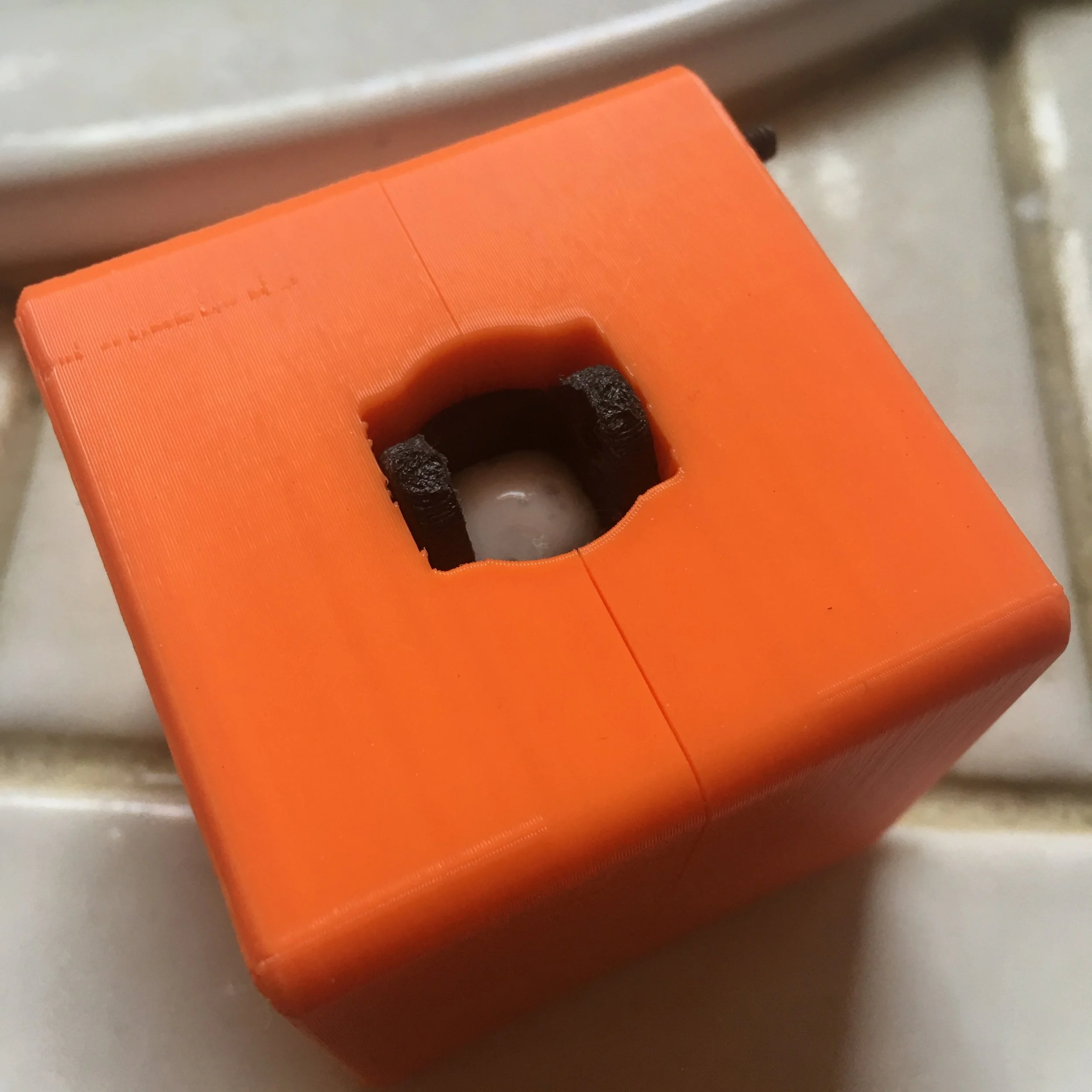
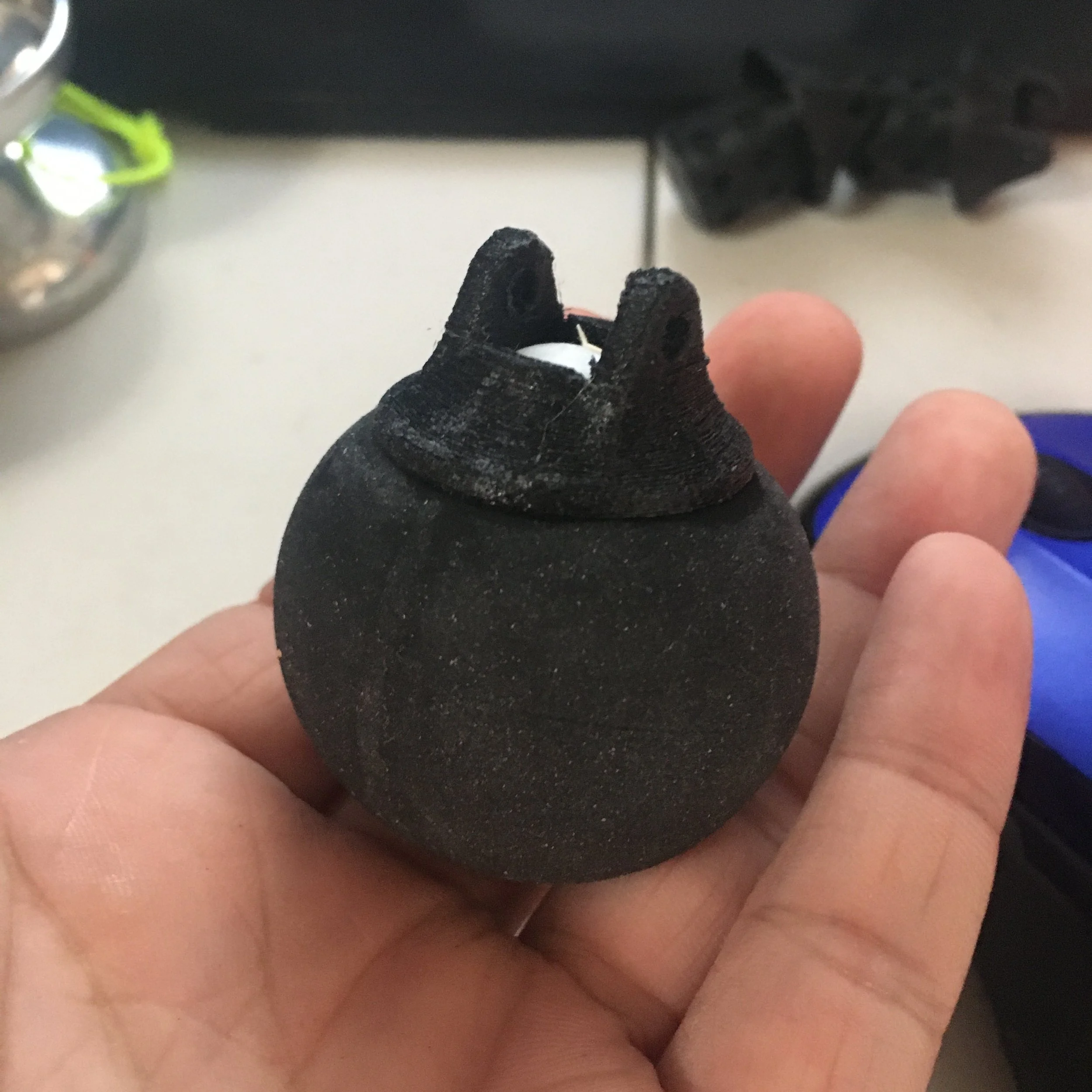
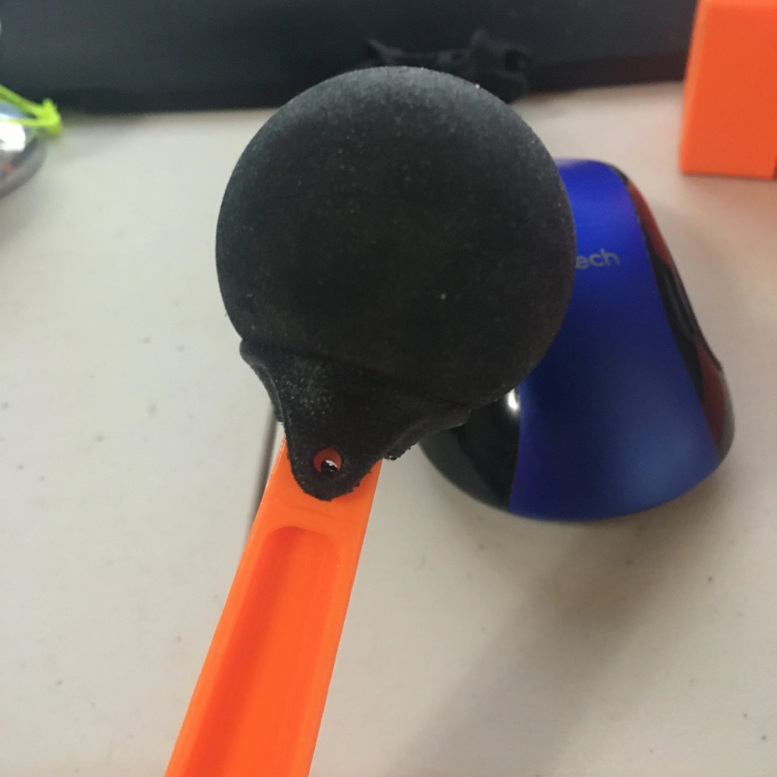
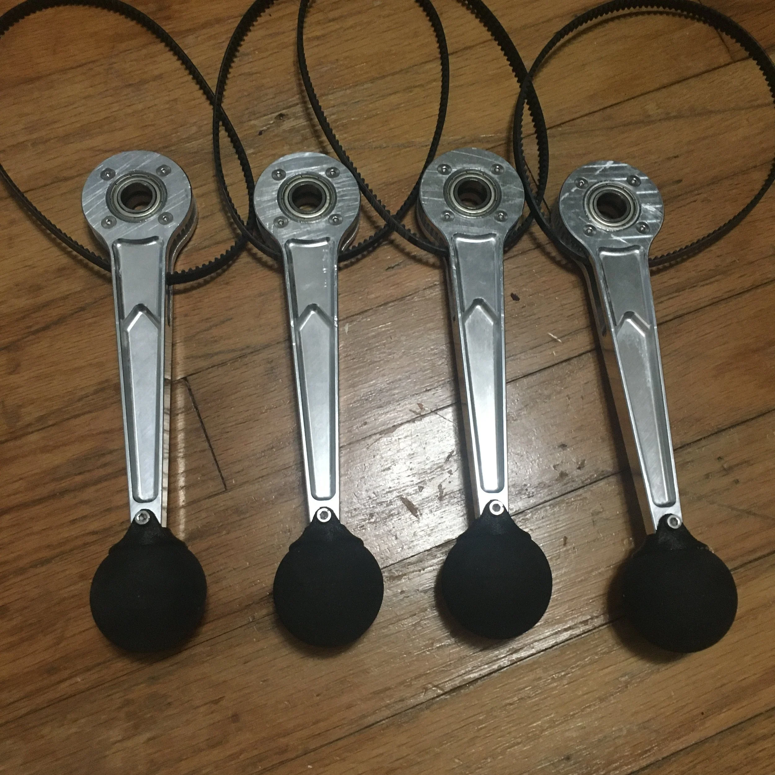
In the meantime I got started on the feet which were made identically to the Mini Cheetah feet. They’re made of a printed core and a squash ball, locked together with expanding foam. One small difference was that the Mini Cheetah feet cores were SLS nylon, but my feet cores were FDM NylonG which I later found out was not watertight to the foam which expanded through the print walls. This was fixed with a razer blade and a few minutes of scraping but good to know for the future.
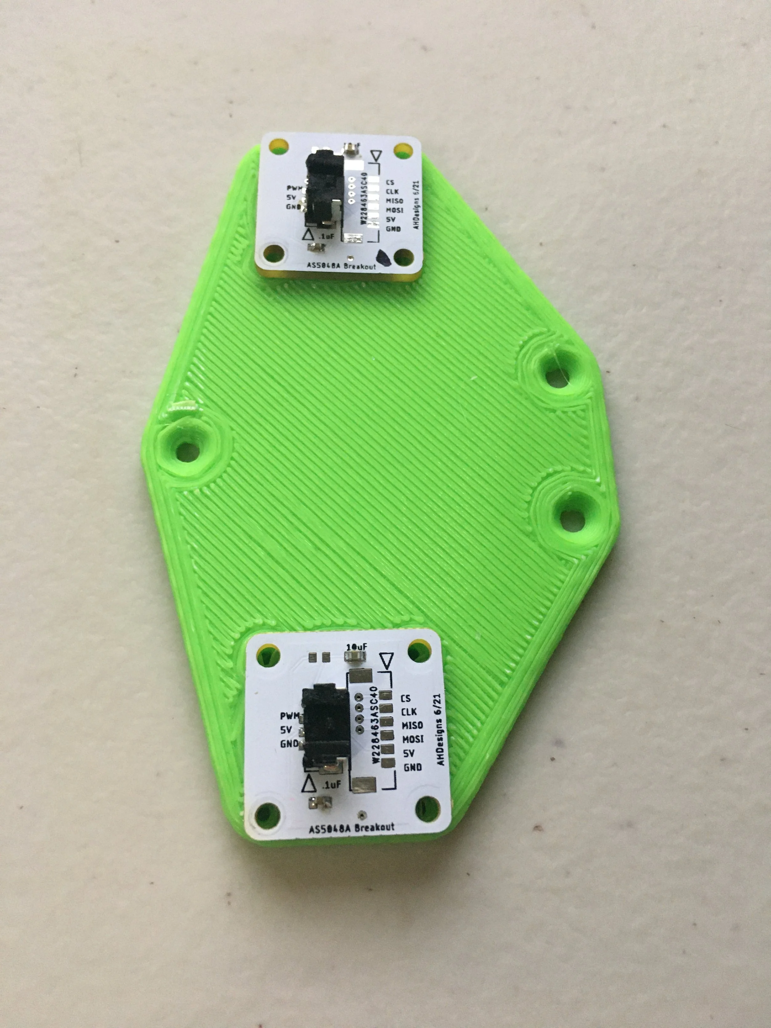
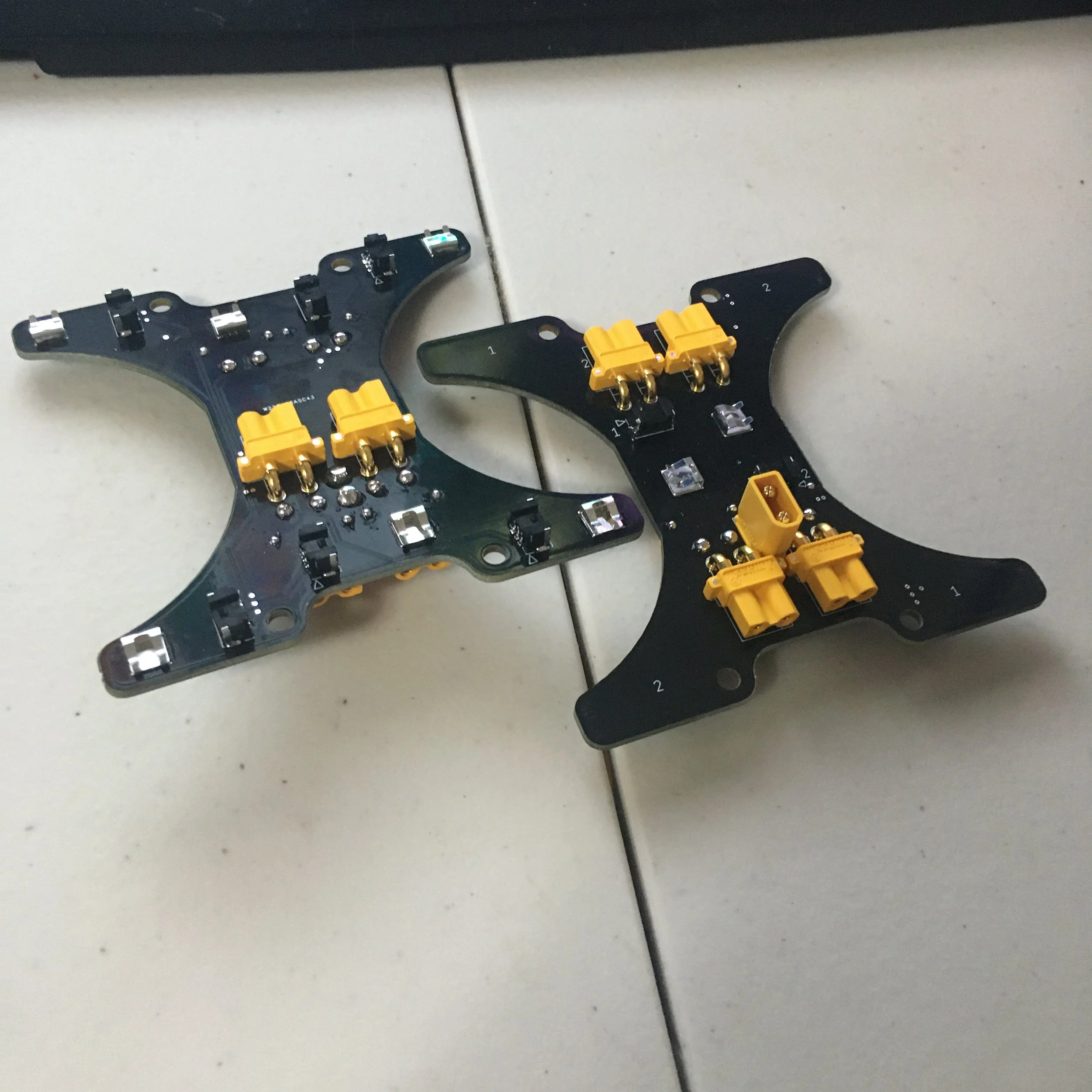
Next I acquired and modified enough controllers for the robot (plus spares) as well as plenty of encoder boards.

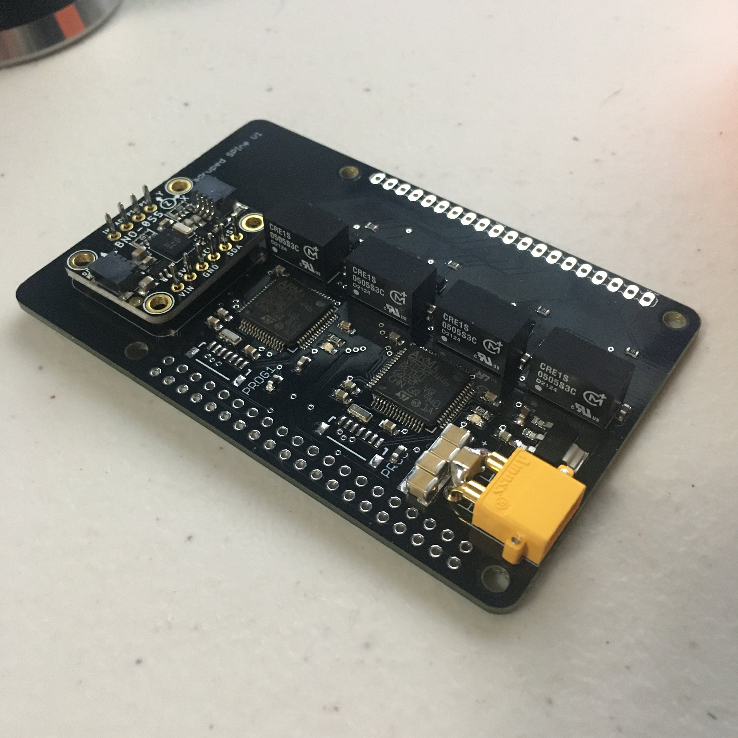
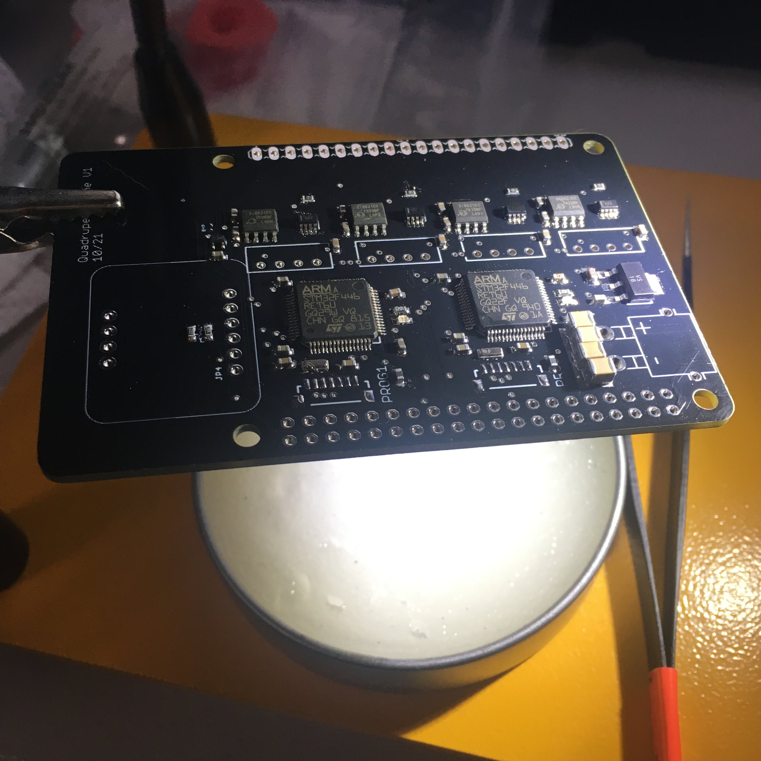
I then made a modified version of Ben’s SPIne board (communicates with the computer over SPI and talks to the motor controllers over 4 CAN buses) that was made using available chips in this shortage, and also had an IMU onboard since I don’t have a $1000 vectornav.
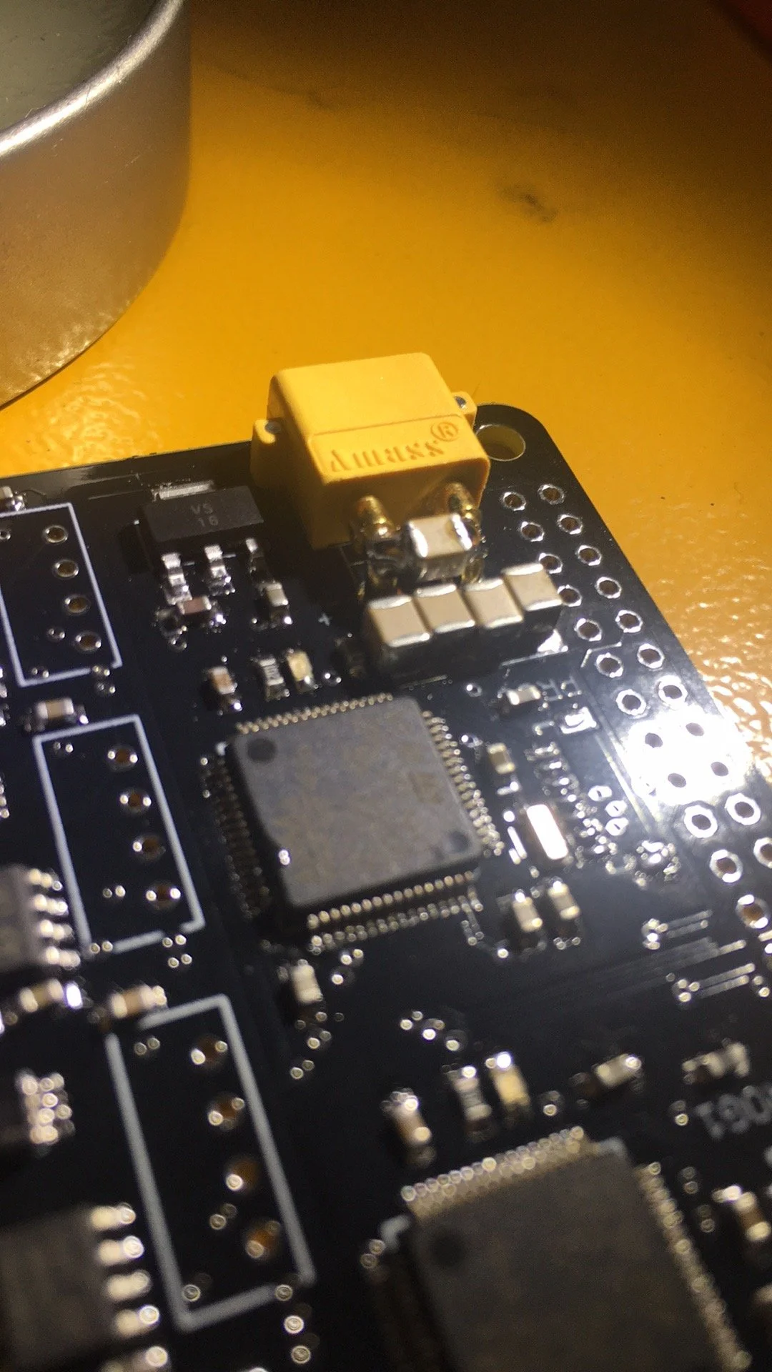
Assembly of the boards was uneventful except I accidentally used 3.3V CAN transceivers and still left the 5V isolated CAN power supplies. Nothing blew up but I had to swap in some 3.3V isolated supplies to get them to work. Also yes I accidentally ordered the wrong size bus cap and soldered the last one between the XT30 legs.
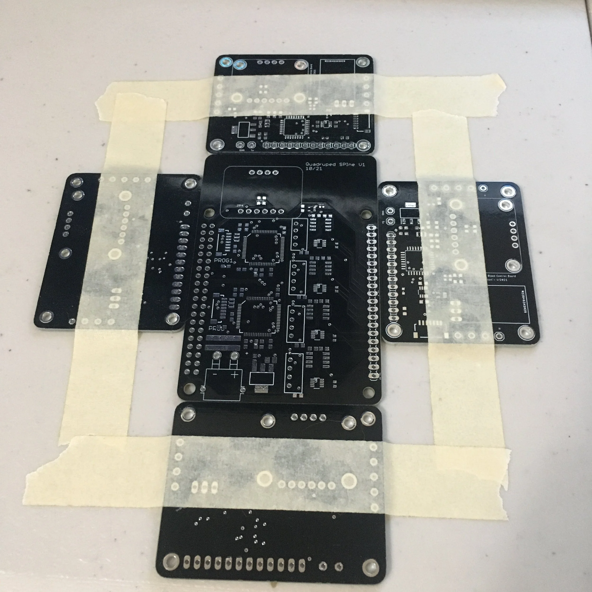
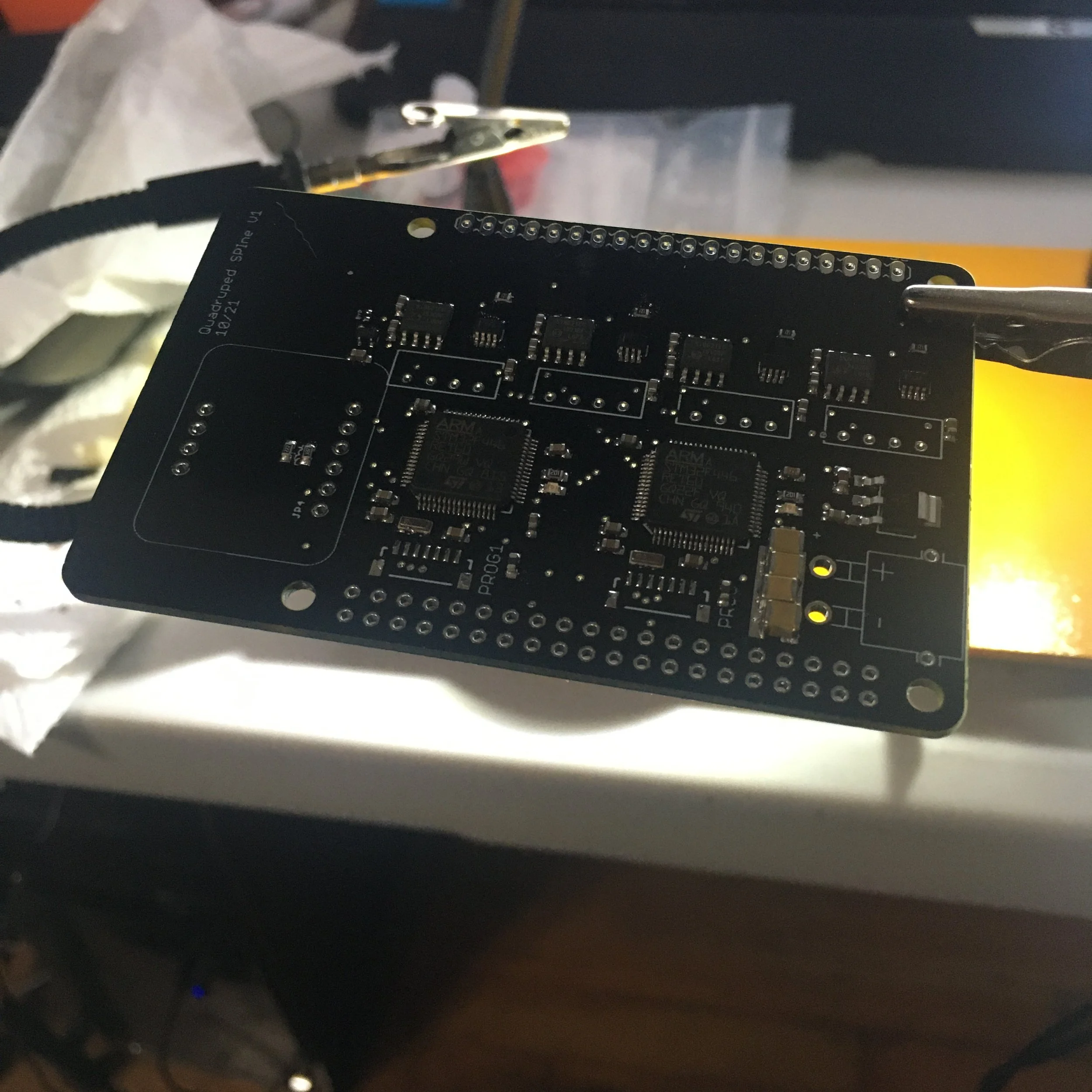
I also modified the connector board which takes in 4 CAN channels and the receiver. Used much cheaper connectors than the harwins.
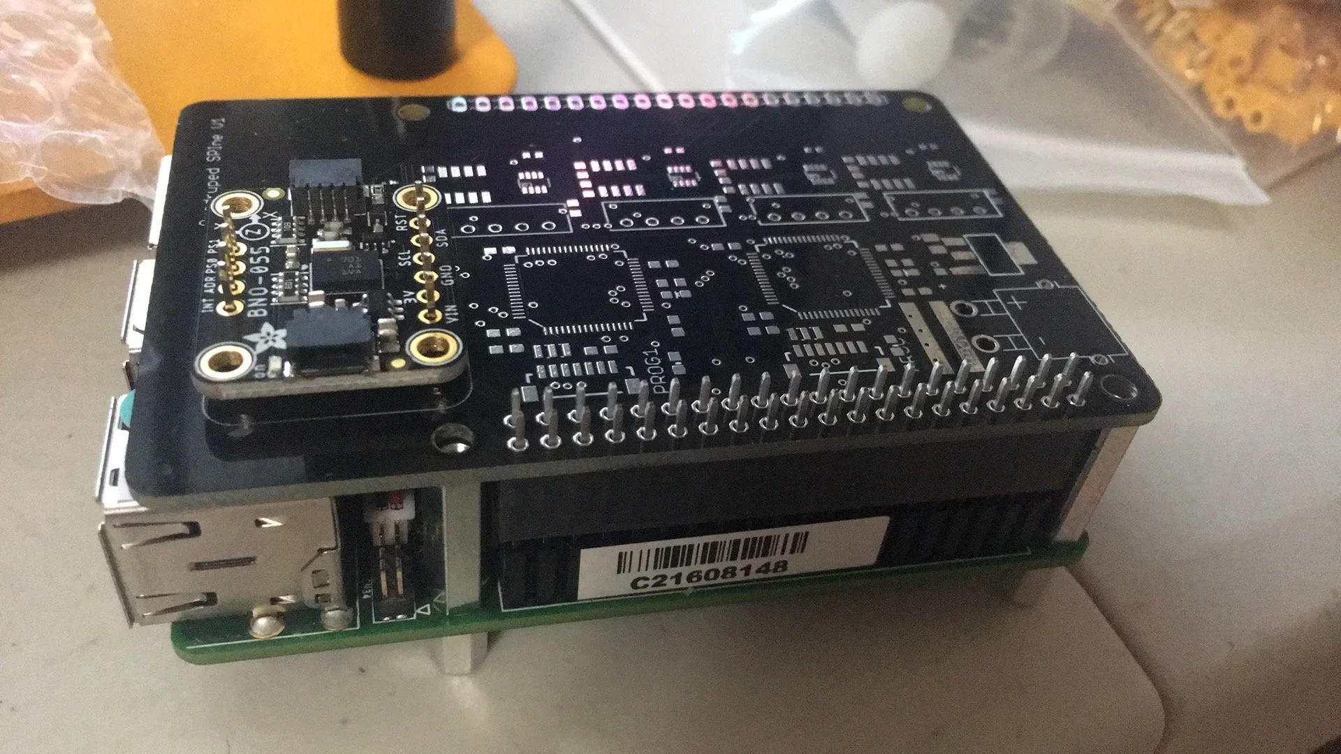
The completed computer stack is a drop in replacement for the mini cheetah computer stack but with connectors that I prefer. It consists of the UP Board (Intel Atom processor), the SPIne board, and the connector board.

Last board I made was the distribution board for the legs. Although my actuators were not modular, I still wanted the legs to be. So with this distribution board, I simply have to apply 1 power connector and 2 CAN connectors to control 2 legs.
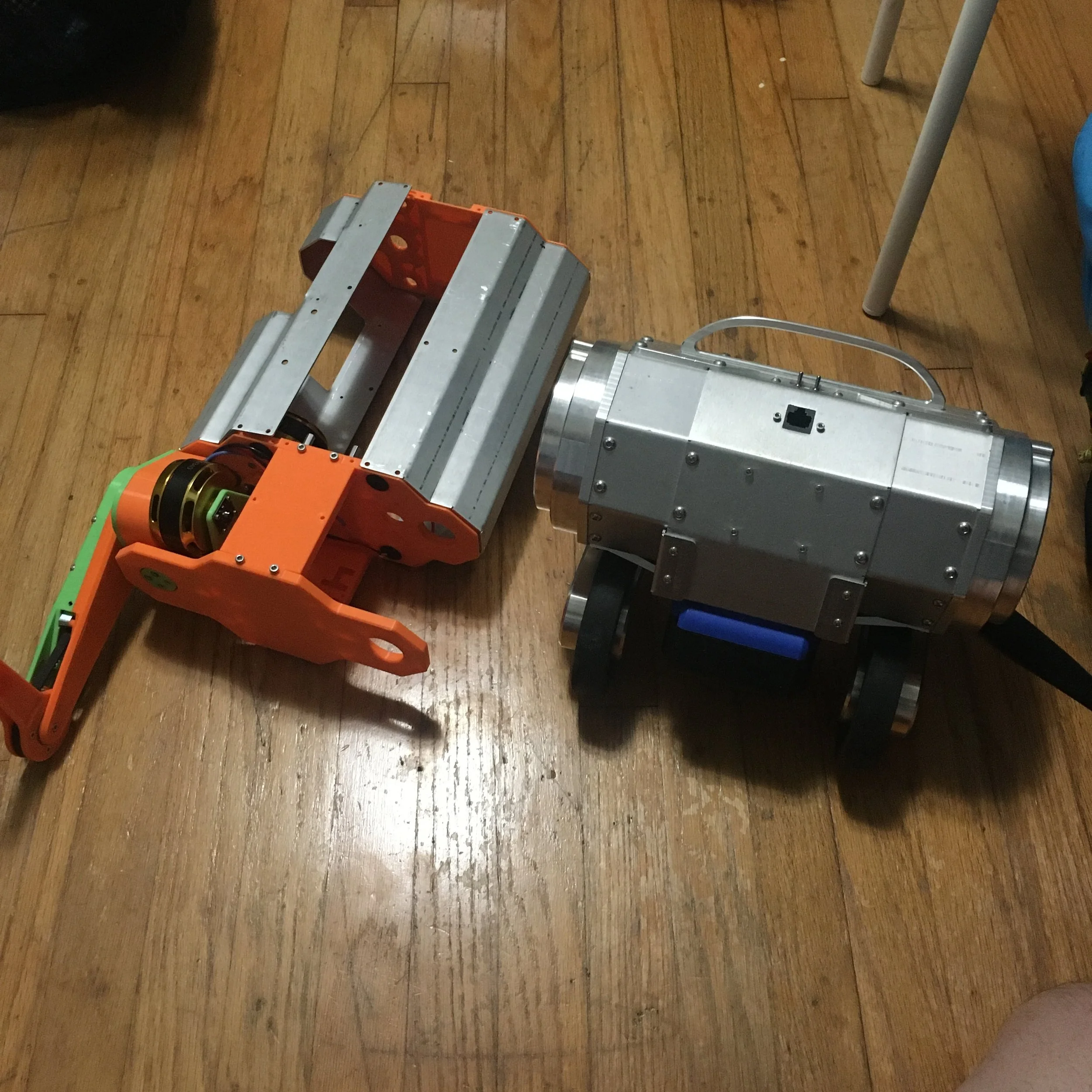
Lastly I order the sheet metal parts and bent the body at a friends shop. Unfortunately while the complicated bends do help with aesthetics and stiffness, the tolerances do add up. The body I bent fit but required some clamps to get on and so I decided to order a professionally bent body from China which I swapped in later. Wheeled biped for scale.
It was at this point that Christmas came a few months early :)
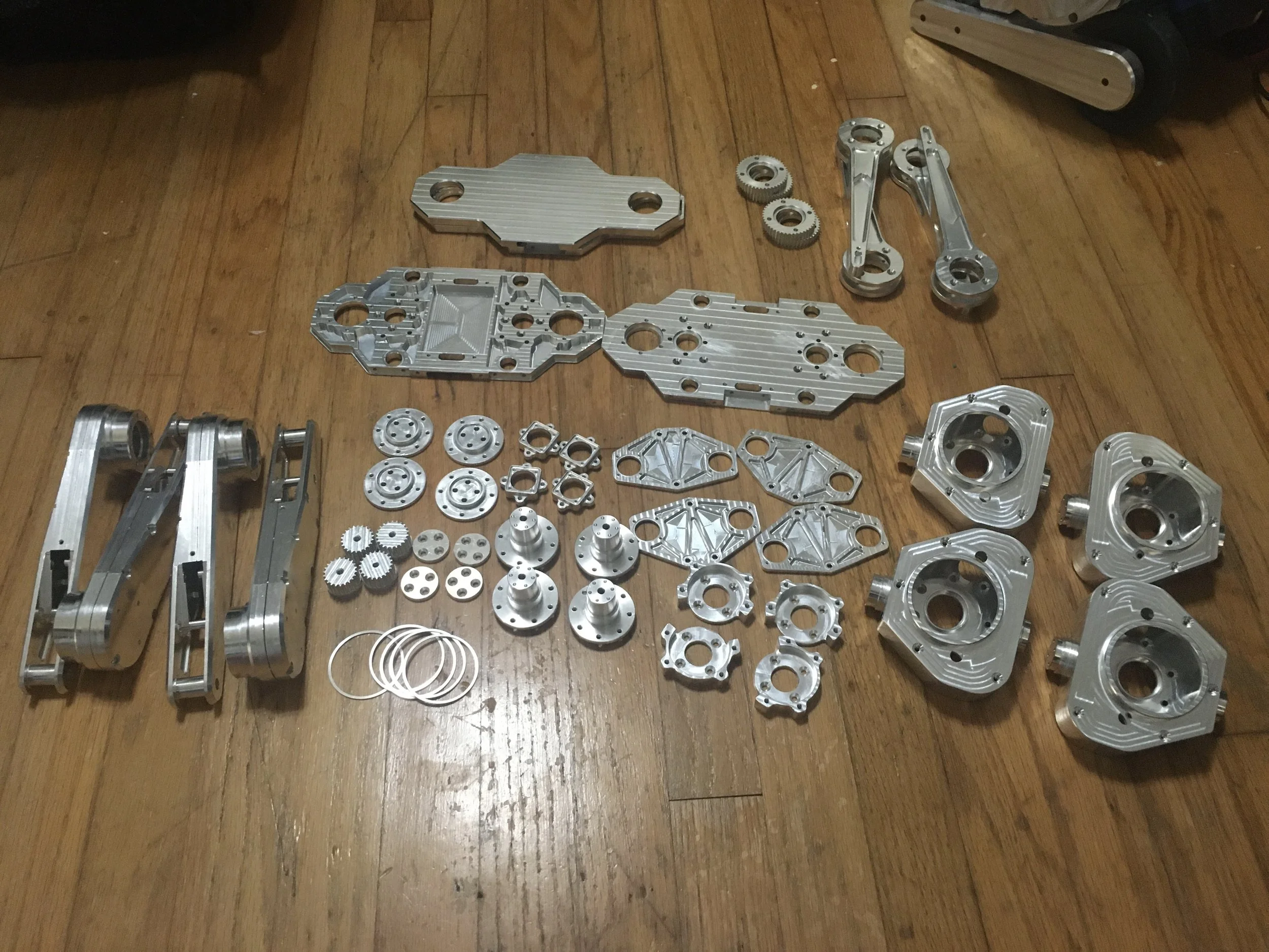
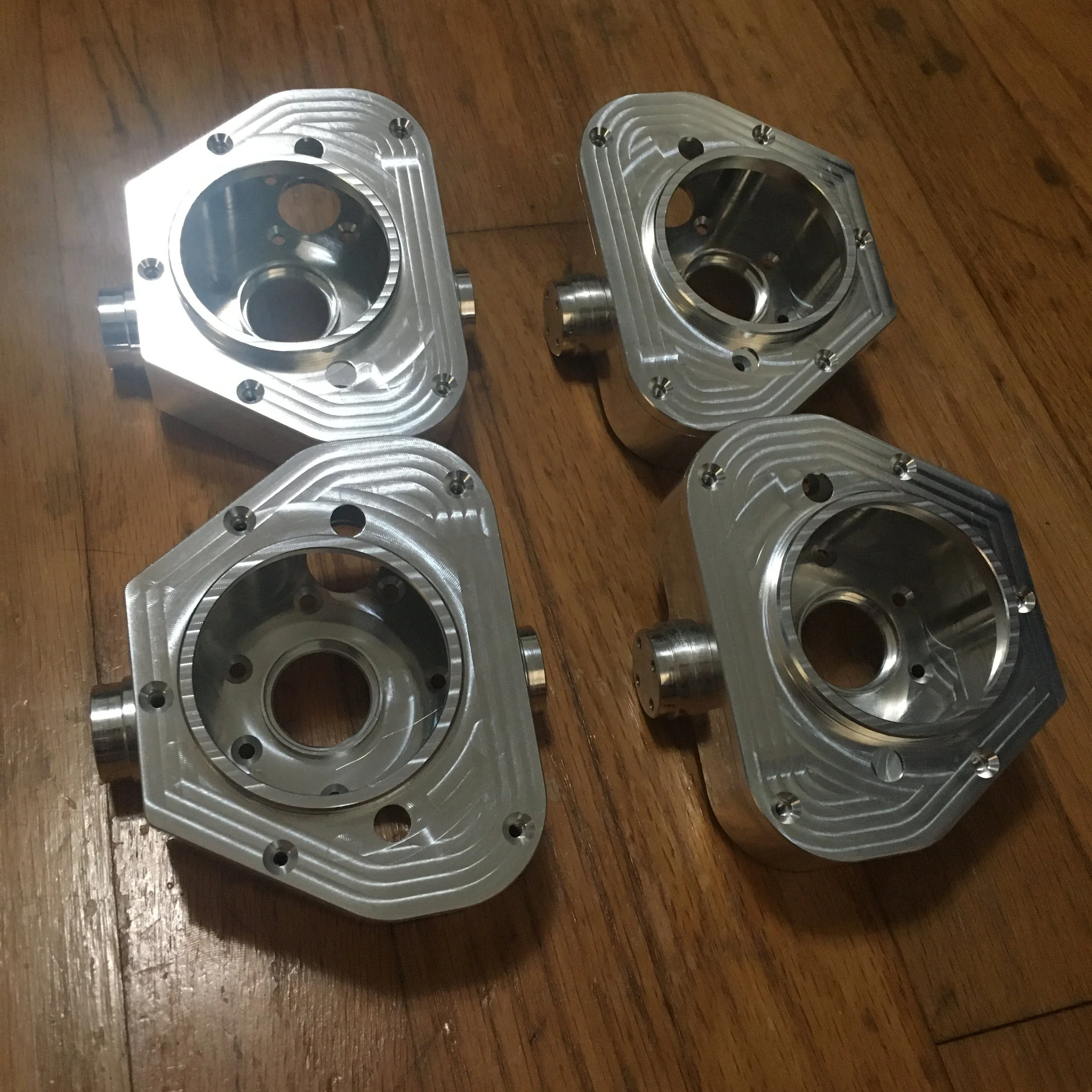
I used a new vendor for these parts but was quite happy with the quality. They hit all my tolerances and so everything went together smoothly. The surface finish on the parts is mediocre in certain places but can’t complain too much.
Here are some pretty pictures
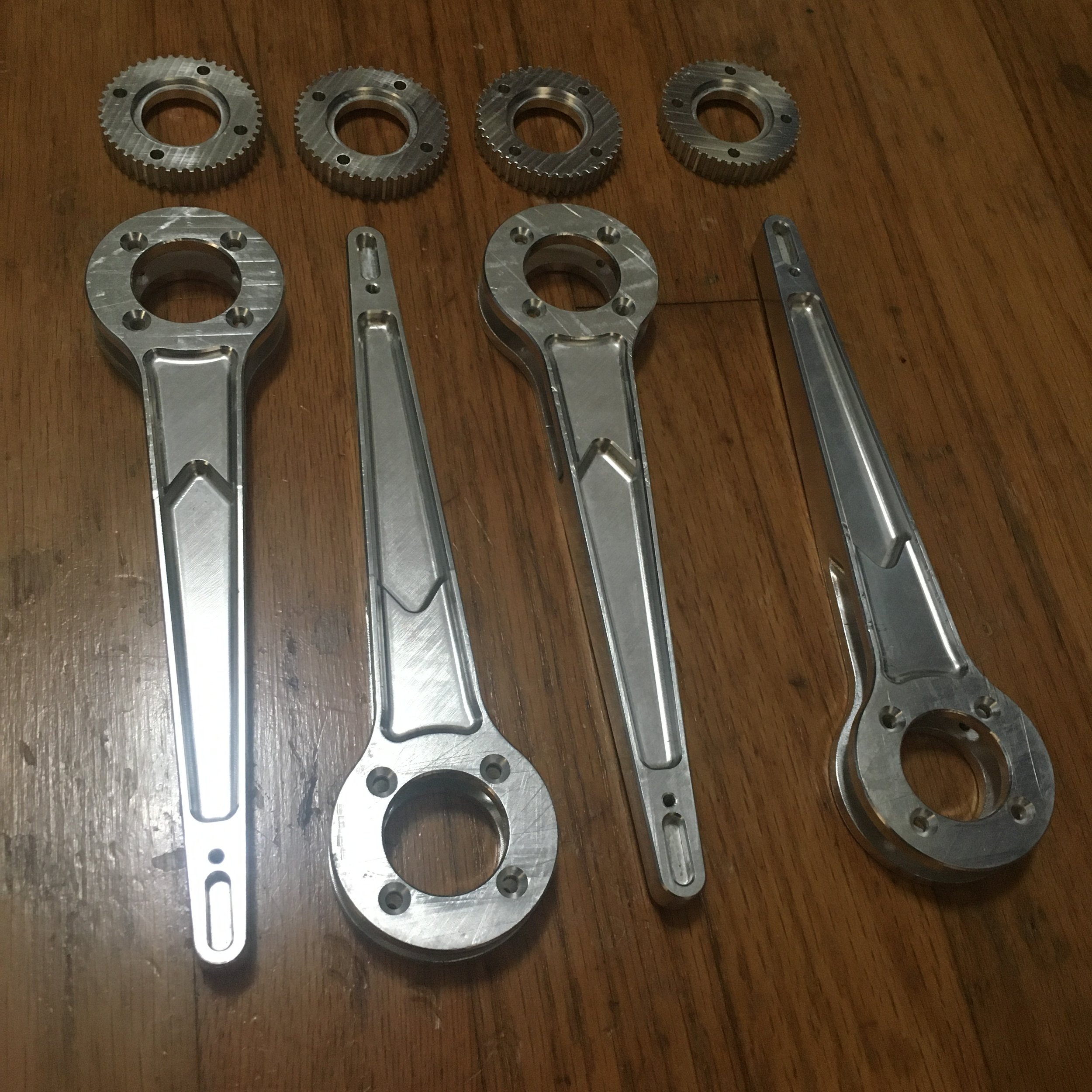
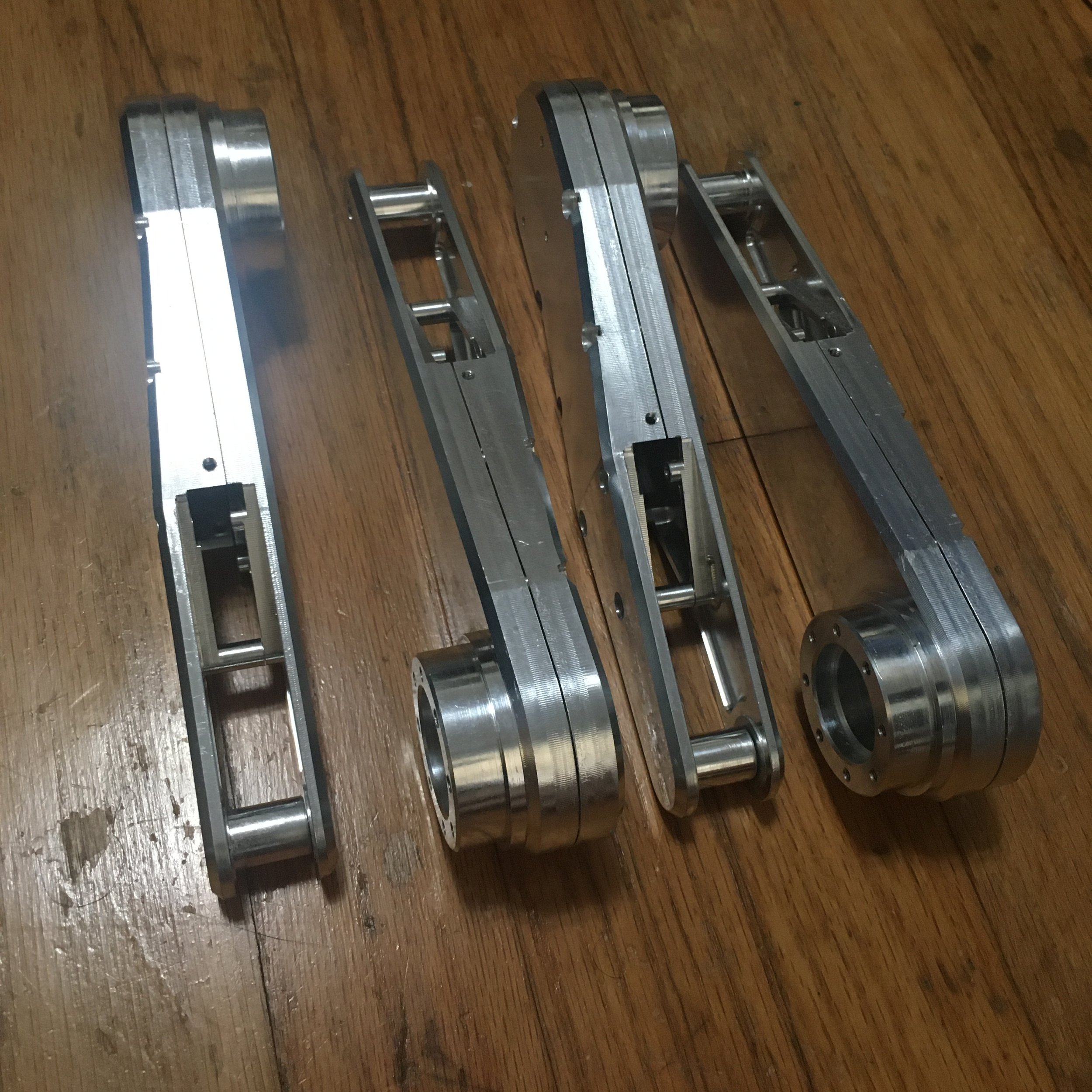
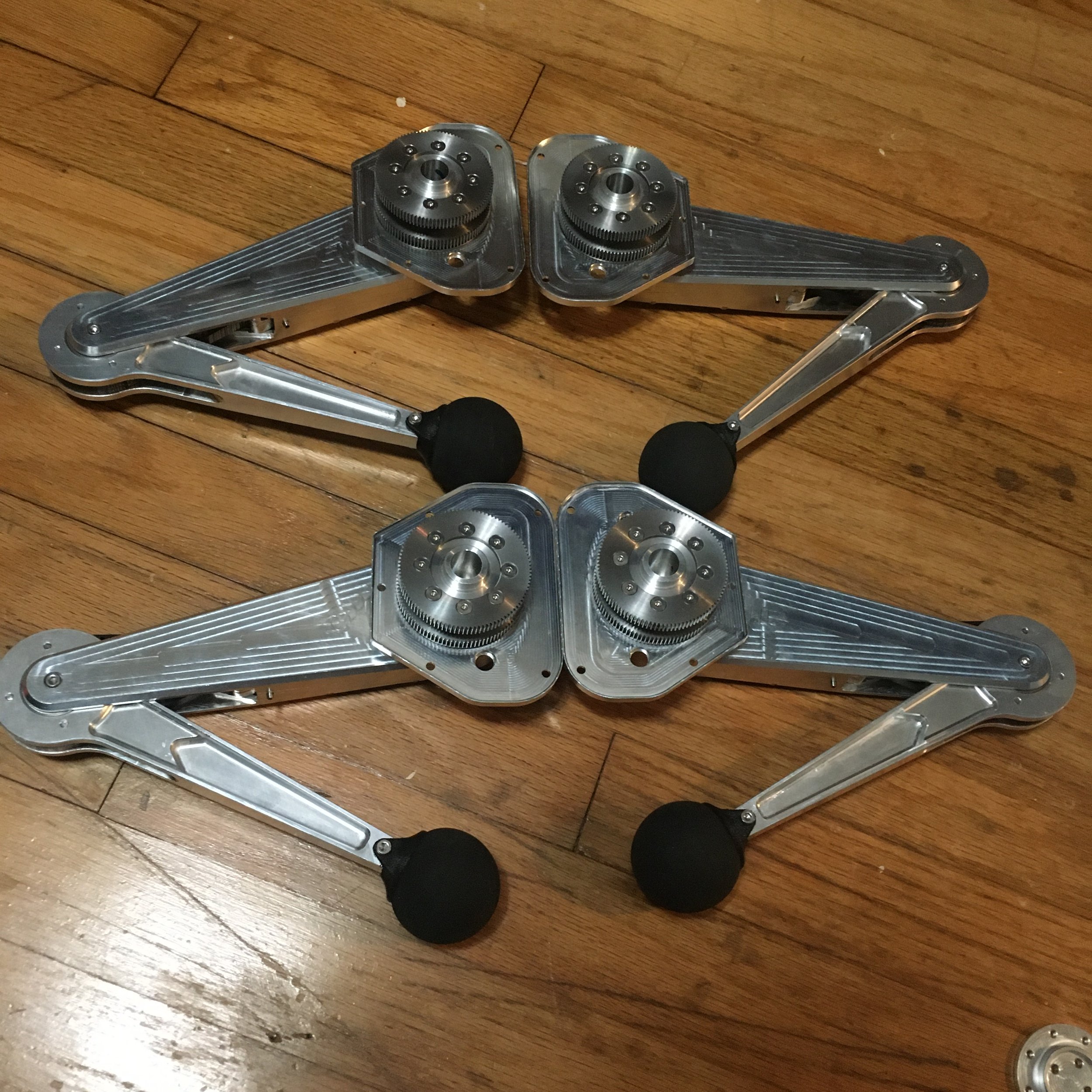
Leg assembly starts with the lower leg, followed by the upper leg up until the hip/knee gearbox.
A bit of repetition and there were 4 legs
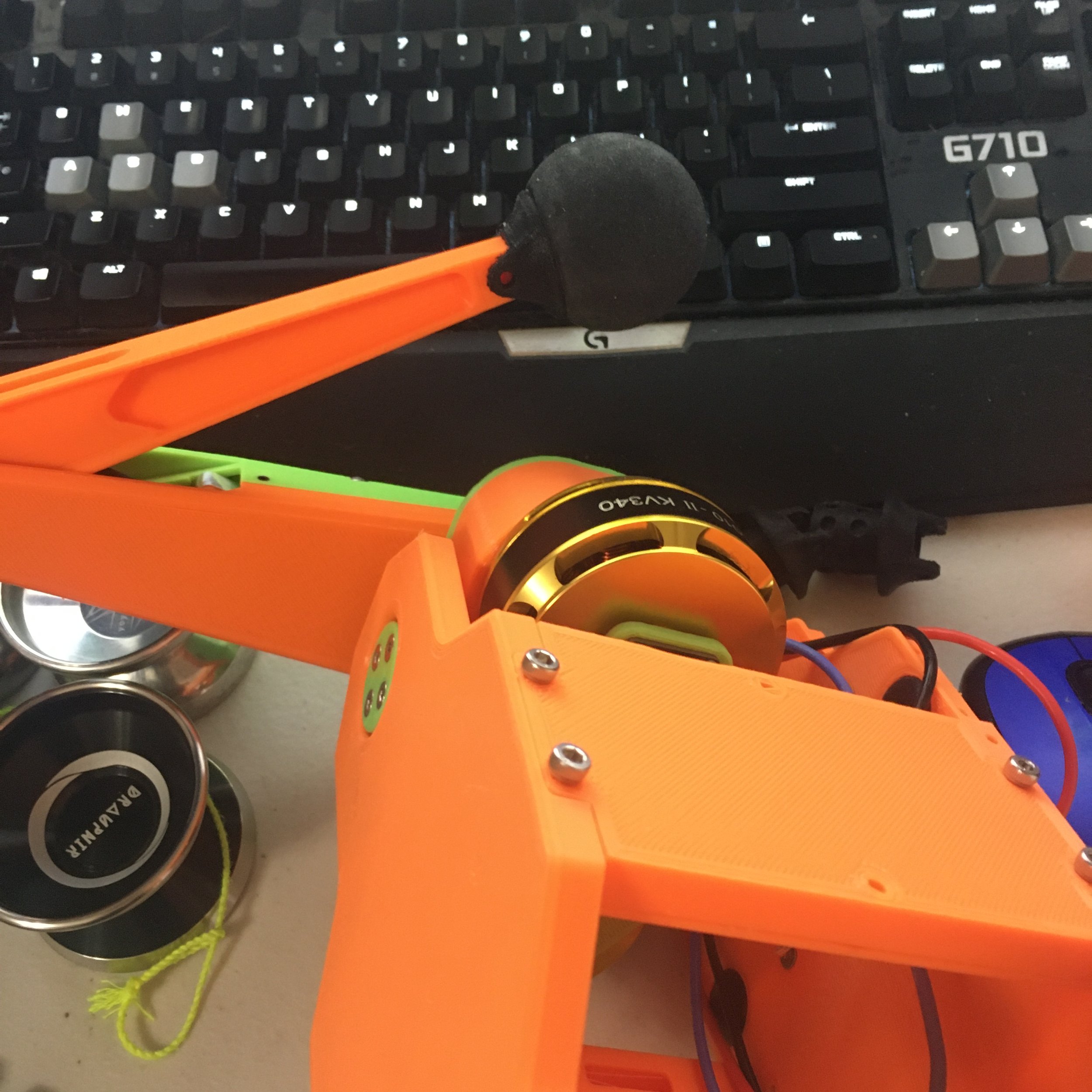
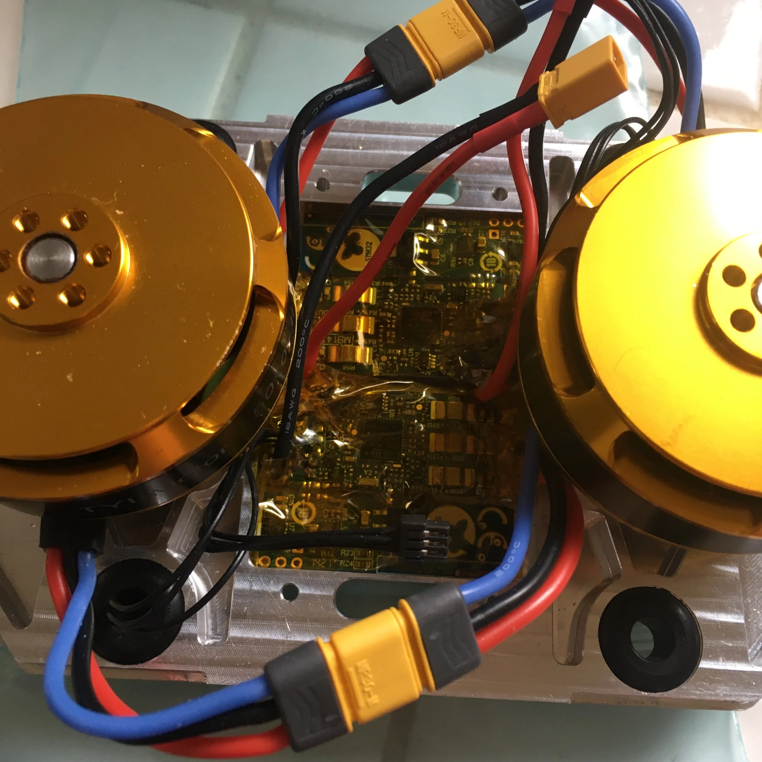
Next I started to build up the hip/knee gearbox. Because this whole blob moves I added abrasion resistance shielding to all the exiting wires
Time for some pretendobot
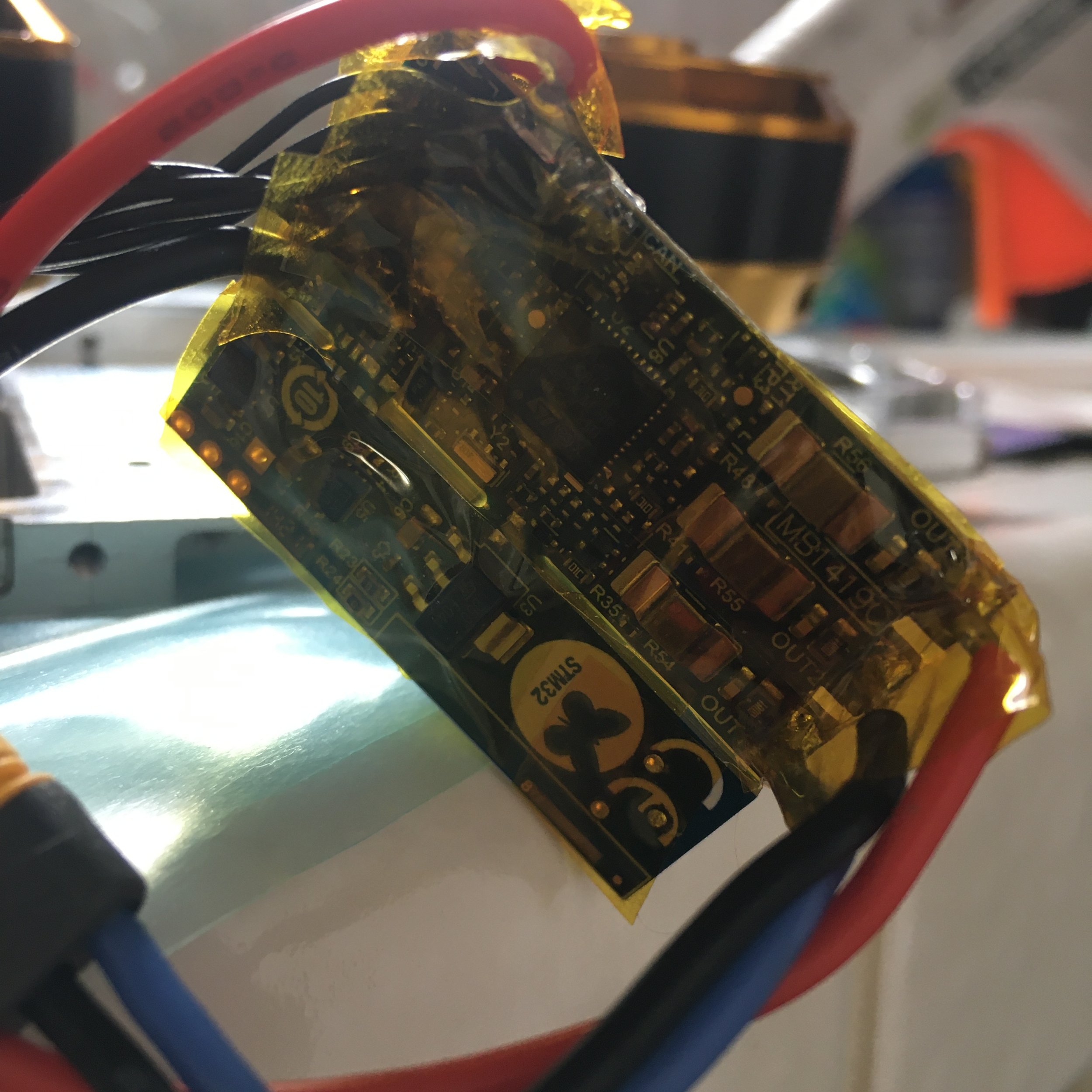
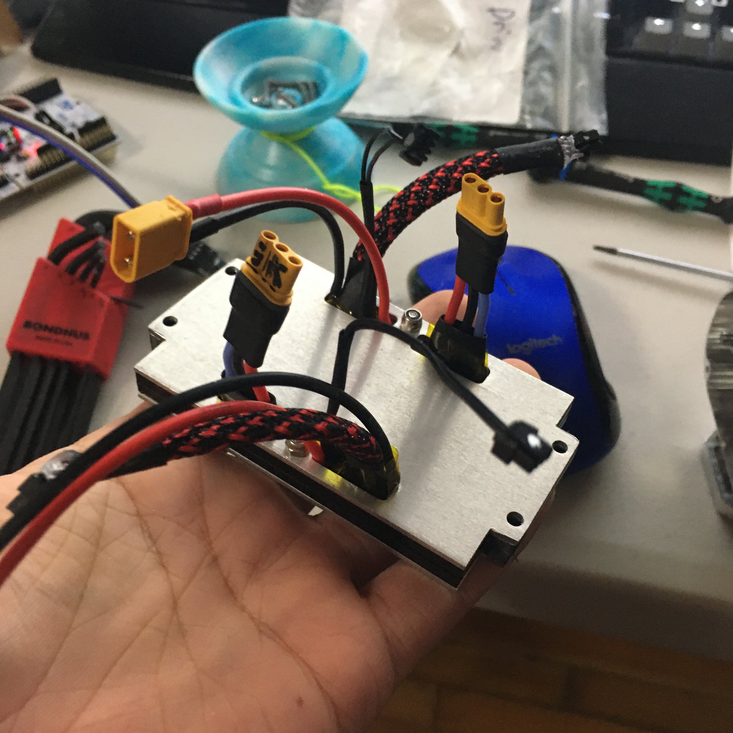
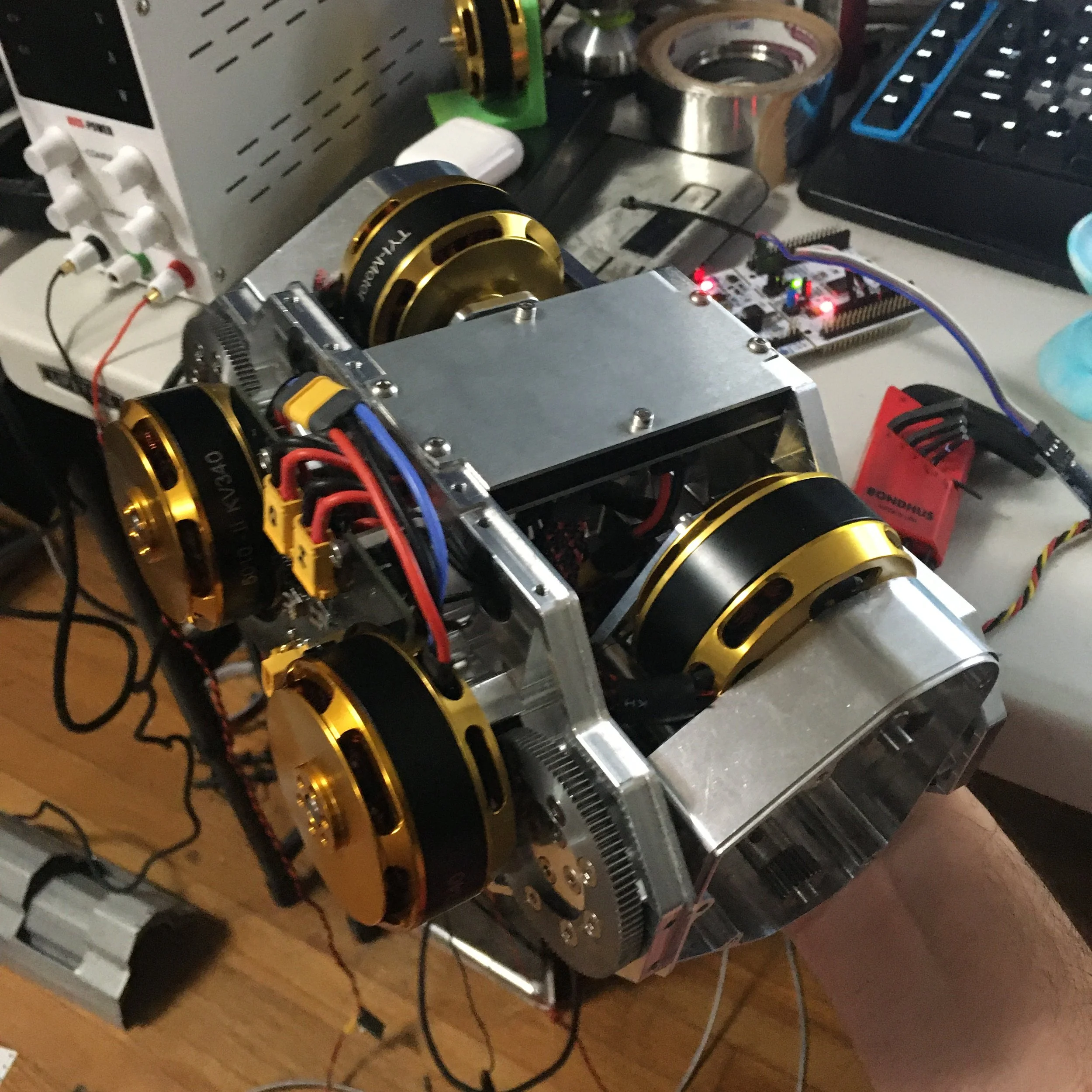
Next it was time for electrical work again. The controllers are all hidden inside the frame for packaging reasons and to use the frame as a heatsink. As a result they need to be very thoroughly insulated. After cutting and soldering all the wires/connectors on the controllers (and testing/calibrating every one in the process), I added Kapton everywhere except over the FETs/gate drives. Thermal pad goes between the high temperature components and the frame.
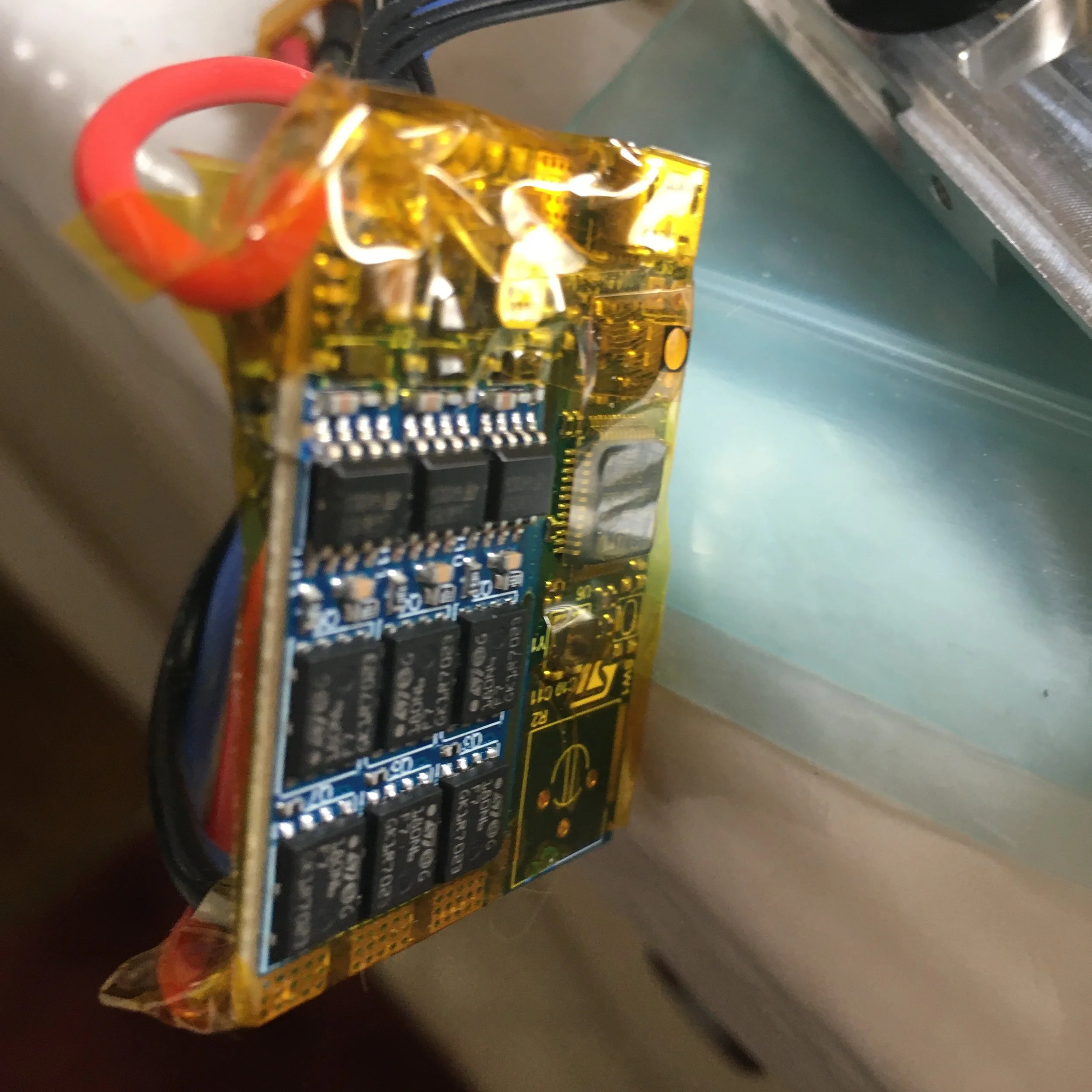
4 hip/knee controllers are hidden in sandwiched plates between the legs, and the 2 abad controllers are hidden between the abad motors in the frame. It was around this point where I relearned how convenient modular actuators are but I think this setup will do for this robot.
Much wiring later and it was finally done (whoops only got a blurry picture). Definitely the most painful process of this project so far.
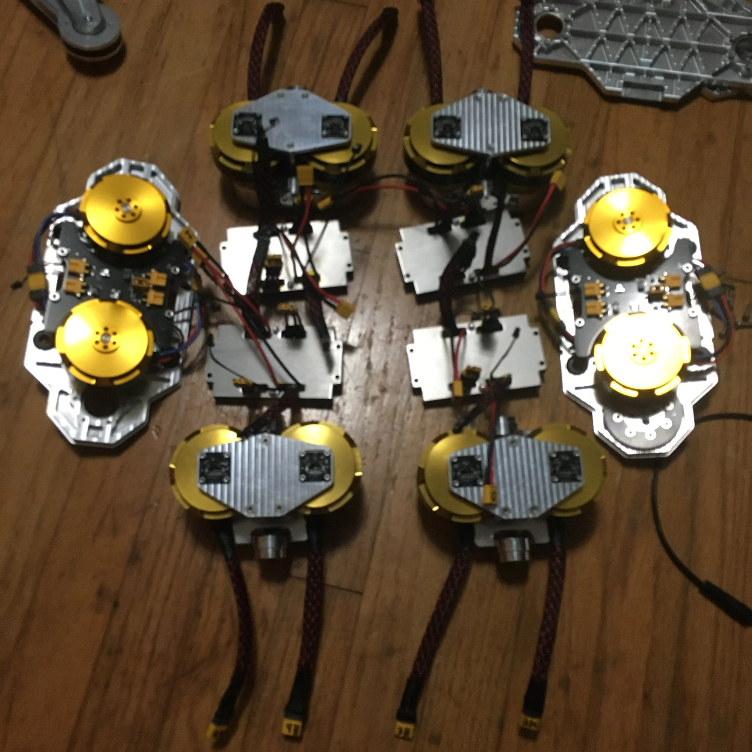
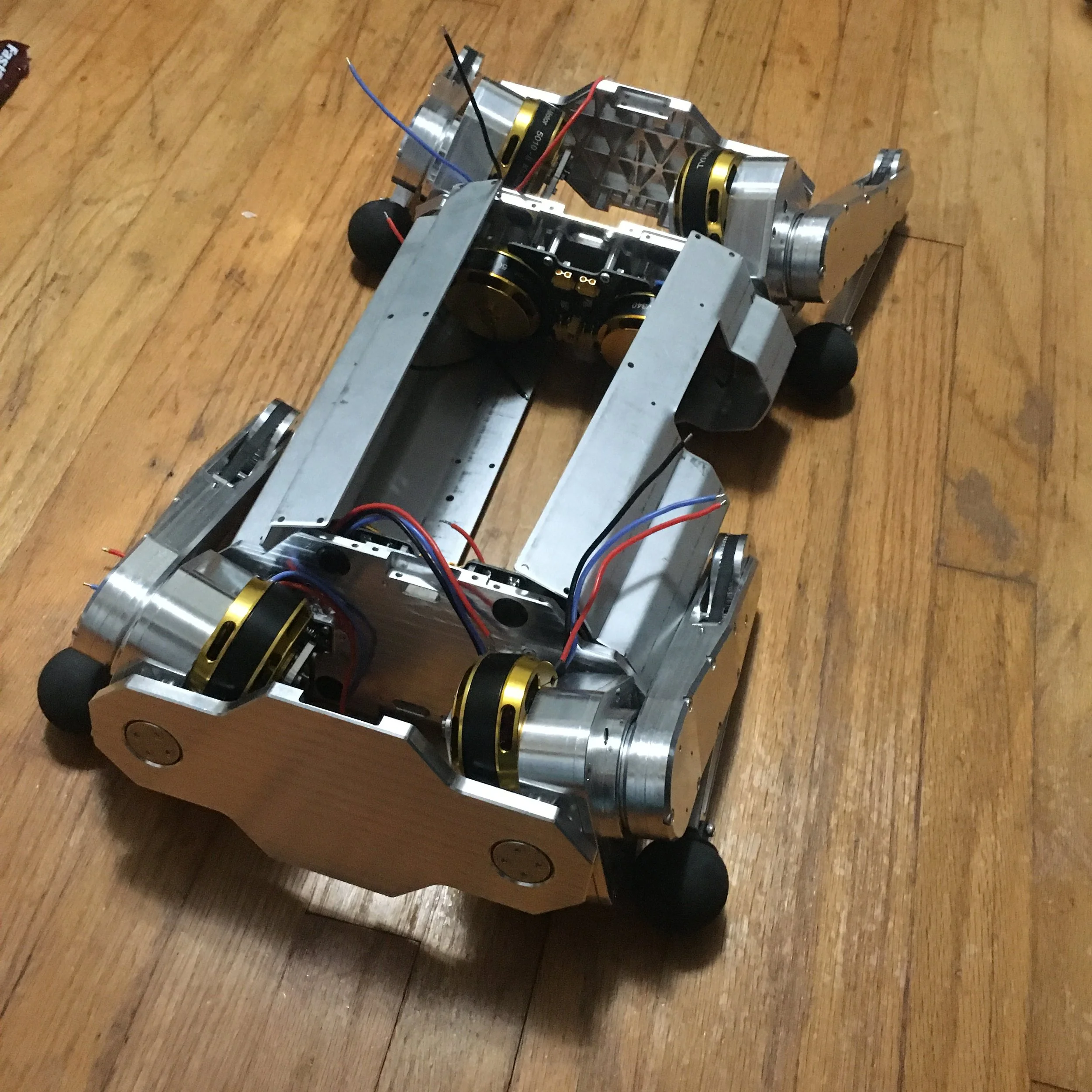
Here you can see an assembled leg unit without the dangerous legs attached for testing. I’m fairly happy with how contained it is, although it was certainly a lot more painful than modular actuators.
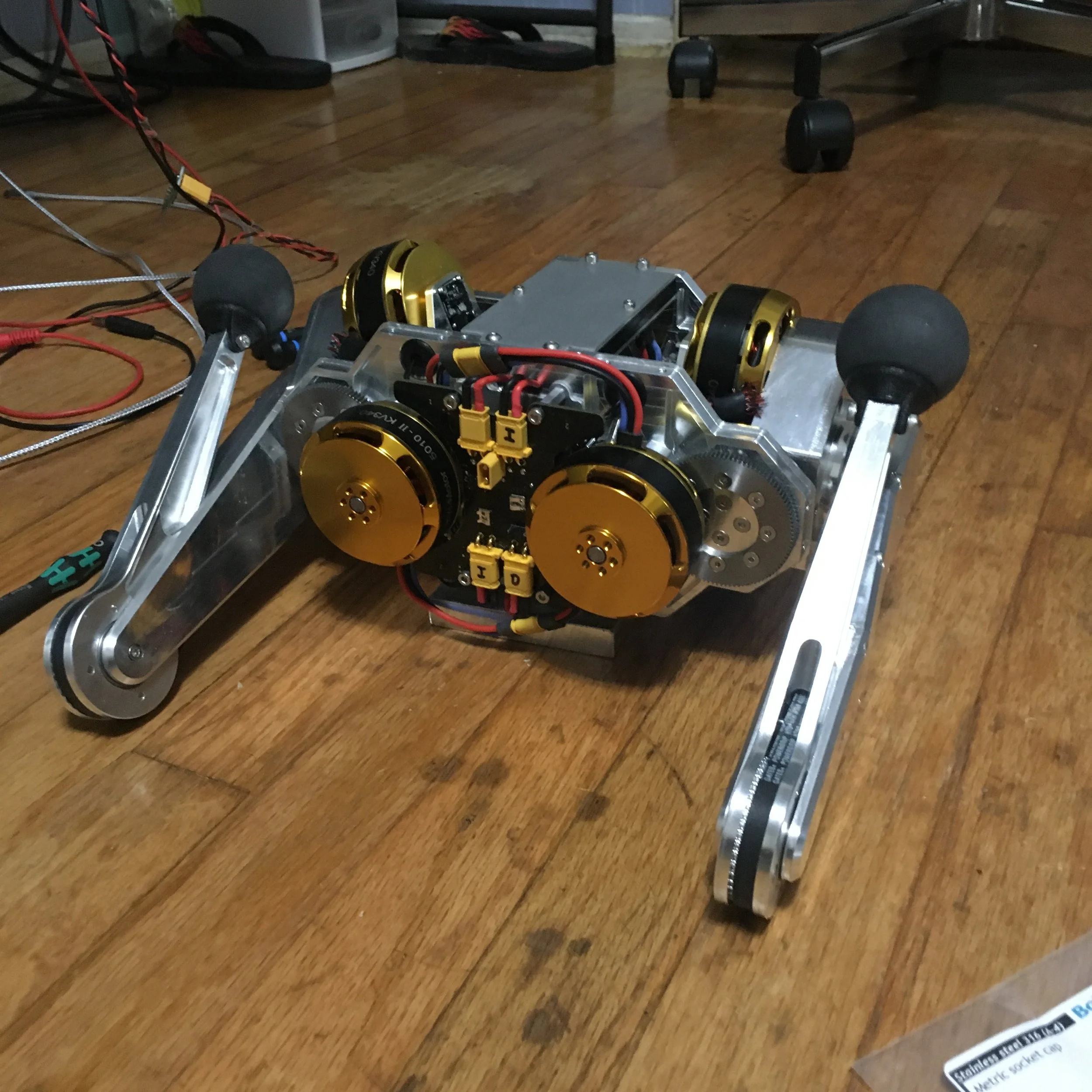
With that I did some final motor controller stability testing and when things worked I attached the legs
I didn’t take pictures but inside the body is another power supply board and a modified bracket that holds the Cobalt battery (just like on Mini Cheetah and my wheeled biped).
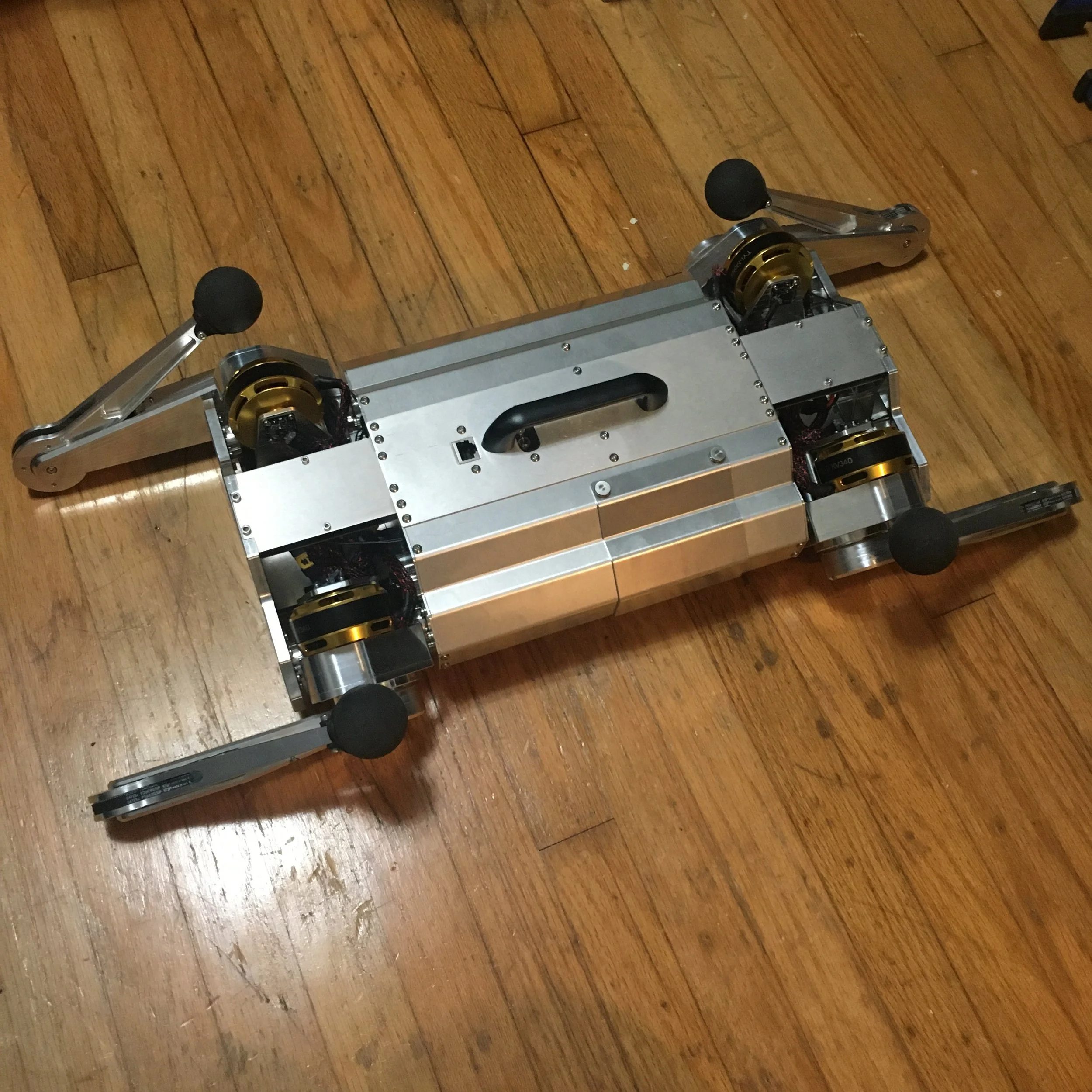
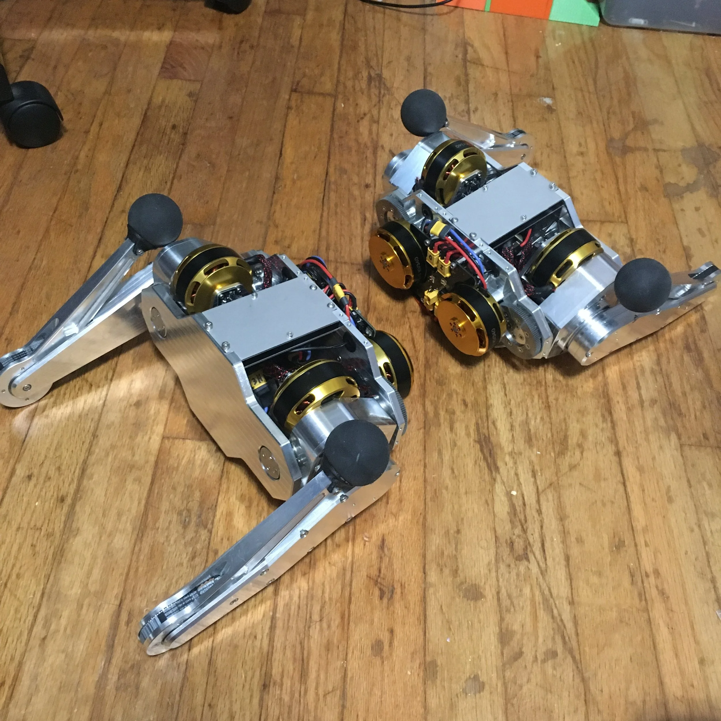
And now here I am with a quadruped with working hardware/firmware! Controls will take a while because I’m busy with other projects at the moment but some day this robot will do a backflip and run around!