
Wheeled Biped Pt. 3 - It’s Done?
My projects over the last few months have been very interweaved since I have limited time, have to wait for orders from vendors (no more piles of parts like in MITERS), and of course I get frustrated/bored and like to bounce around depending on what states the projects are in.
But my pride and joy of a project has been this wheeled biped. I’ve learned so much from working on the Mini Cheetahs with in lab and this project was a way for me to apply so much of what I’ve learned over the years. I’m really happy with how it turned out. I wish I had gotten to do this as my part of my master’s thesis but unfortunately my time in the shops at school were cut short because of the pandemic and so I just did it at home in my free time!
Of course I had plenty of F303 register diddling help from Austin, debugging and moral support from Jared, and help with the motor controllers and inspiration for the whole project from Ben!
On to the robot!
I had designed this robot last year when I first got back home, and figured I would machine it when I got access to tools at work. Fast forward a year, and while I don’t have access to work tools yet, I have my very own CNC mill in my garage! A slight problem is that I’m limited on my work volume, and so I redesigned the robot to have all parts fit on my Dyna (while I also finalized the design you can see on the older posts!).
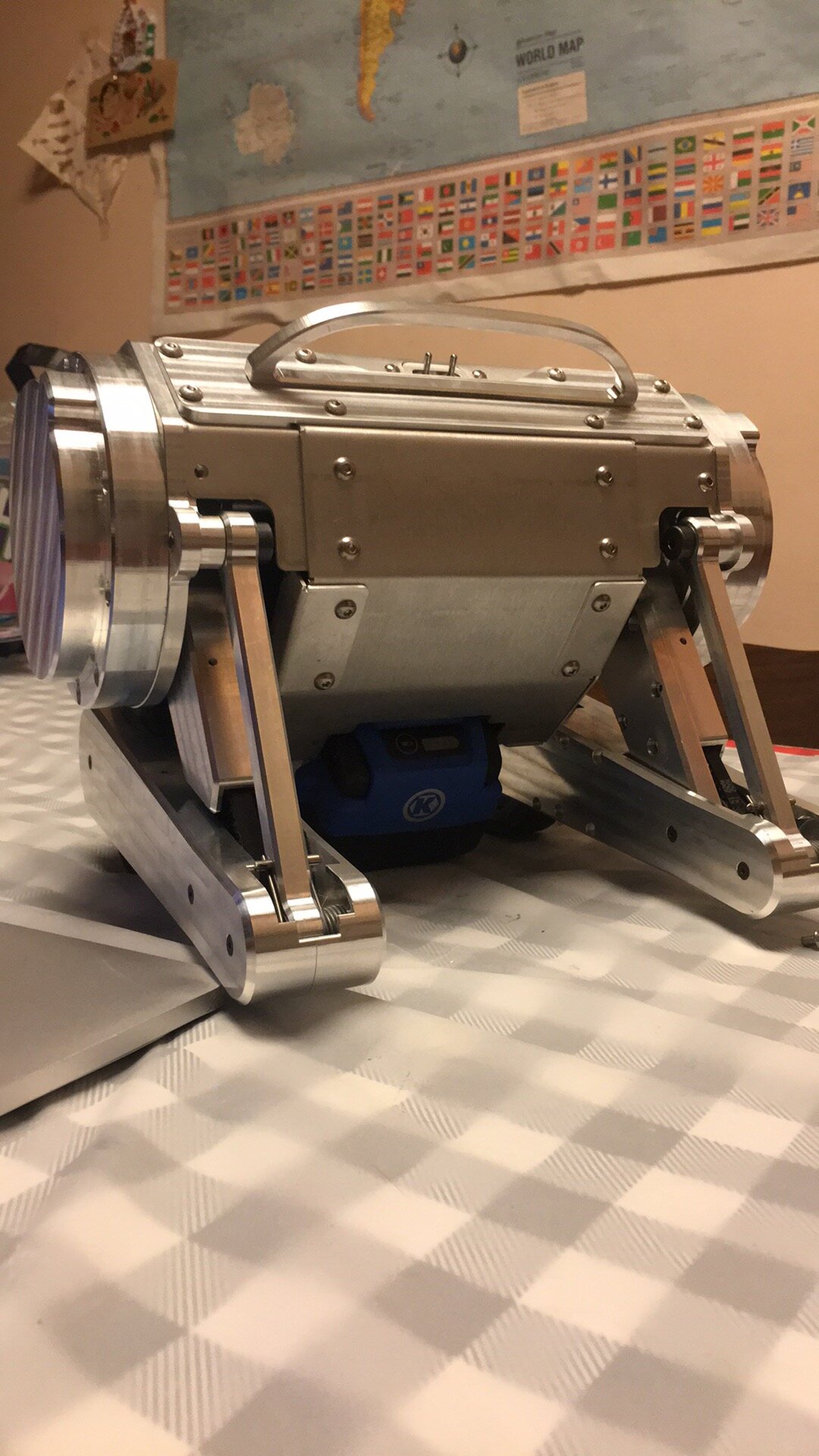
Without further ado, here is my take on Ascento, with obvious inspiration from Ben and Mini Cheetah!

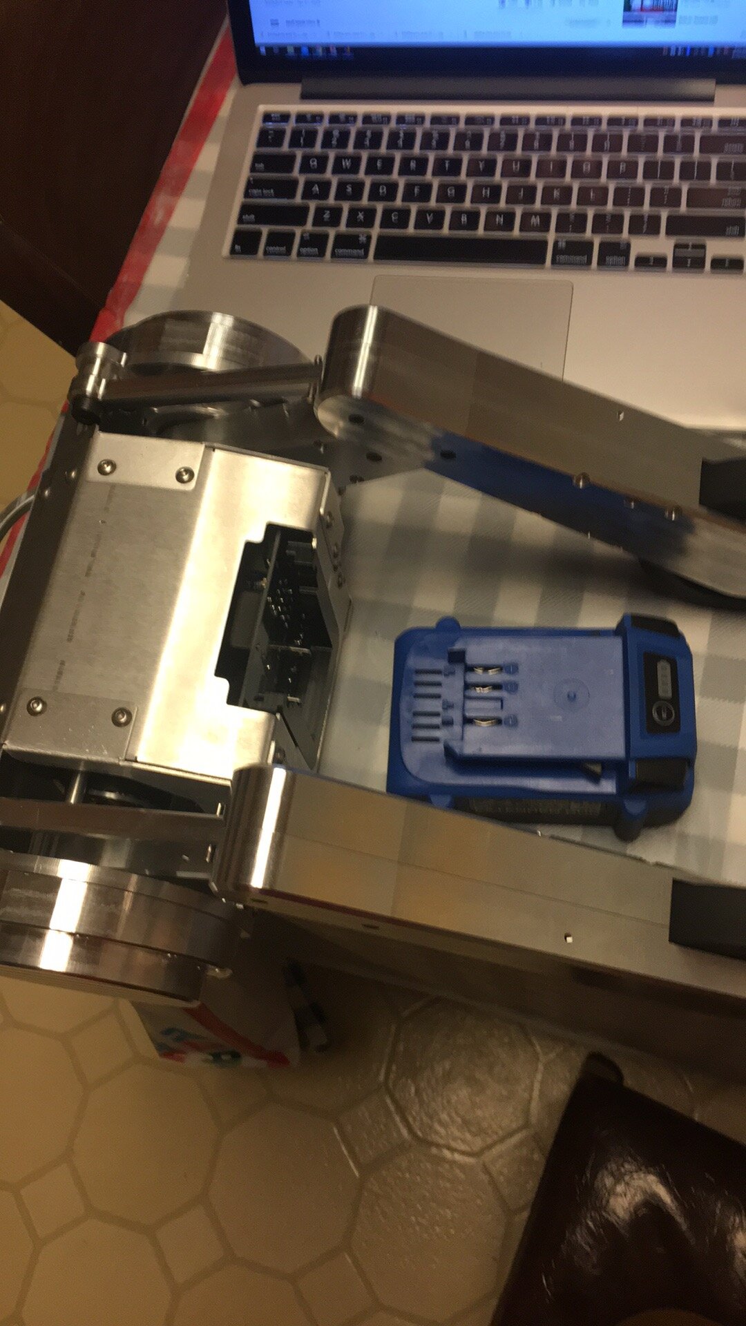
The actuators are coaxial, and the wheel is driven by two stages of belts. This keeps the moment of inertia for balancing high which is nice. Just like Mini Cheetah, the robot is powered off a Kobalt power tool battery which makes for abundant replacements, nice charging, and ease of swapping.
The frame is primarily milled 6061 billet (including the handle!) and the body is 5000 series sheet metal (from SendCutSend) for ease of bending.
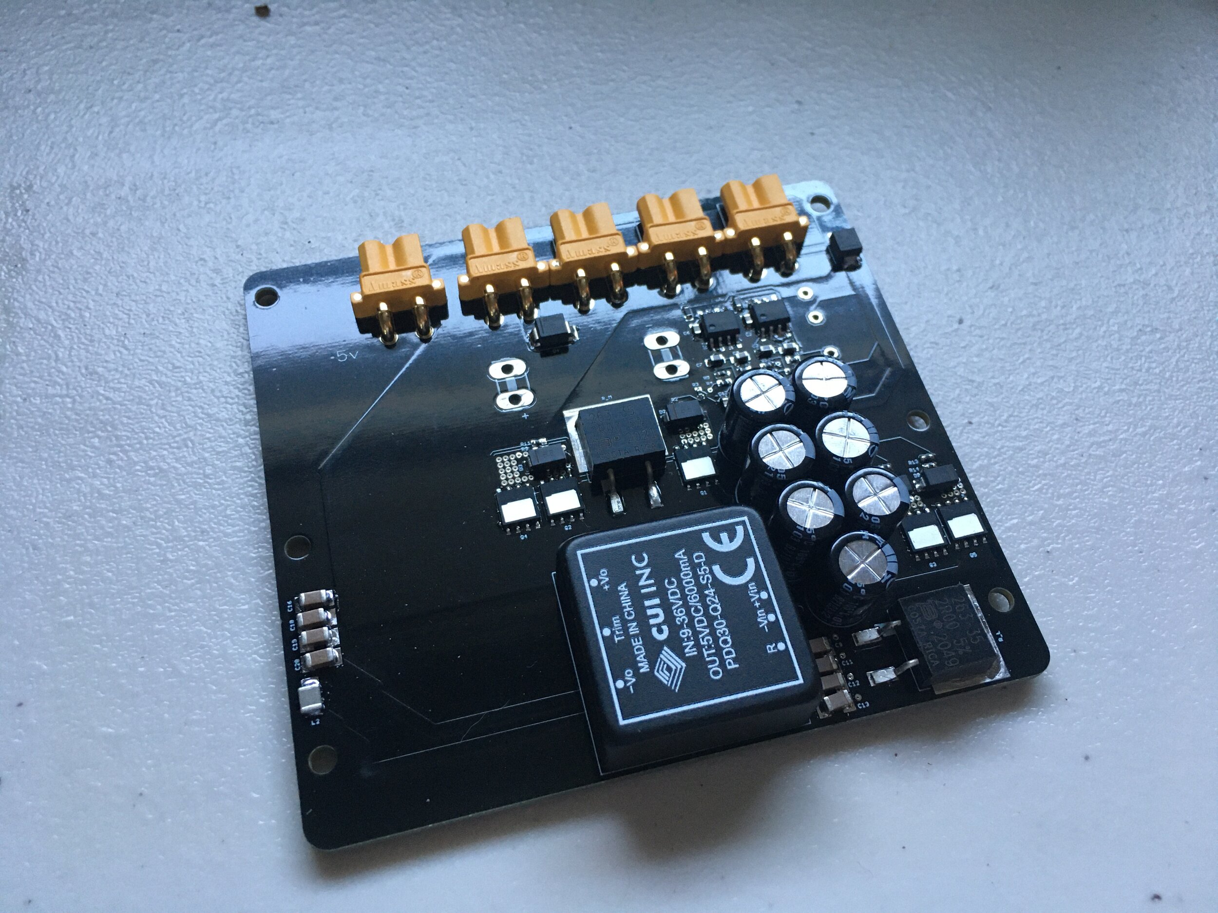
I modified Ben’s Mini Cheetah power supply board for my purposes because it has some nice features like an isolated 5V supply, and precharge. Ben uses 0402s when possible which I thought would be difficult to solder with my heatgun, but I had very few problems luckily (and I assembled 3 of the power supply boards for future projects). On the bright side, it made my 0603s seem massive!
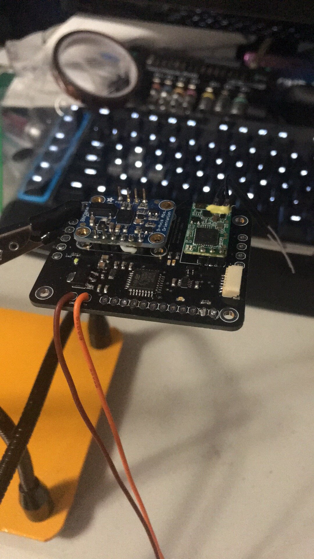
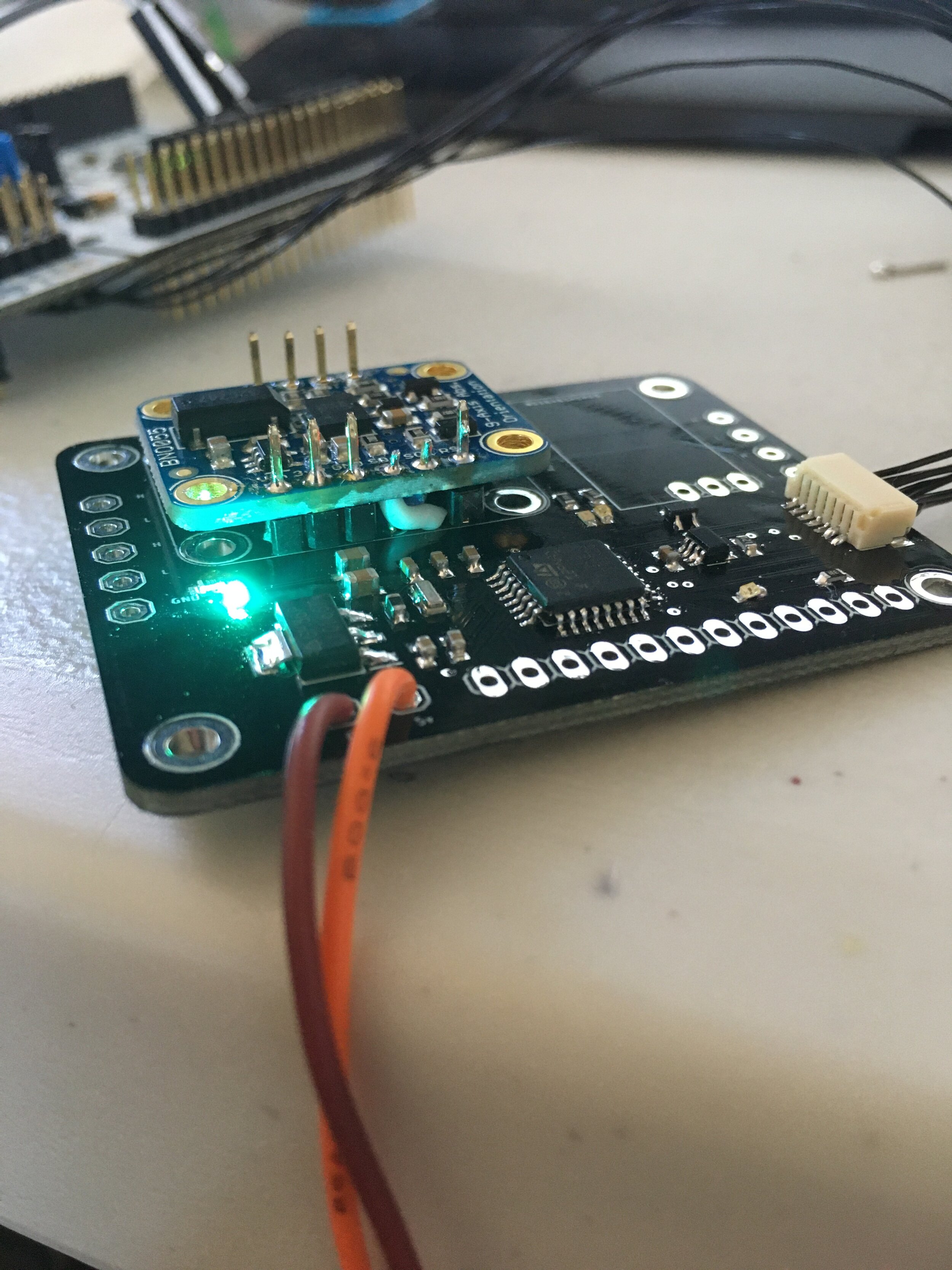
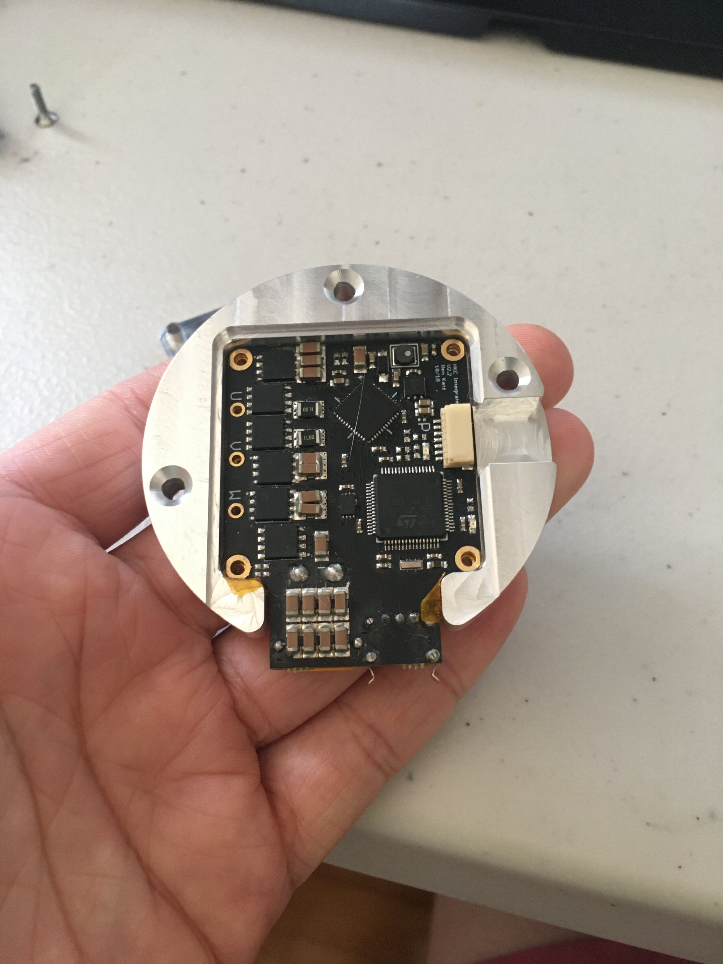
I also laid out my own control board which took my classic BNO055 IMU, an SBUS receiver, a CAN transceiver for talking to Ben’s motor controllers and in this case an STM32F303 to control it all. I accidentally flipped the SDA and SCL pins on the IMU so in the picture you can see a peek at the wire that helps me fix that.
On to some pretty pictures! All the parts were milled by me on my CNC, or turned on the lathe.
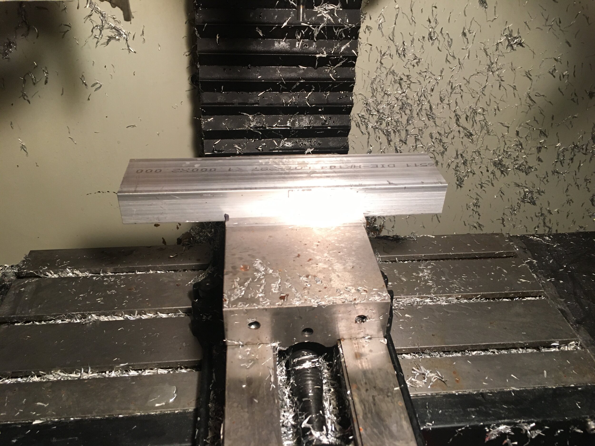
Since this was my first time machining in almost a year, and I had only made 2 parts on this machine since I turned it on (granted it had been < 1 week since the electrician came to install the 240V), I decided to start with the small parts first.
I ran into the same problem on this Dyna as the MITERS one which is that the BT30 toolholders stick and sometimes cause the toolchanger to jam. As a result I haven’t been using the toolchanger and just use tools number 7-99 instead. As a bonus, I get ~4” more of Z clearance which I’ll take any day over the toolchanger. Since I was using many of the same tools, I printed these toolholder holders to keep track of tool numbers. Basically everything is cut with my trusty 3/8” alupower endmill which leaves a gorgeous surface finish, and finished with a 3/16” chamfer mill.

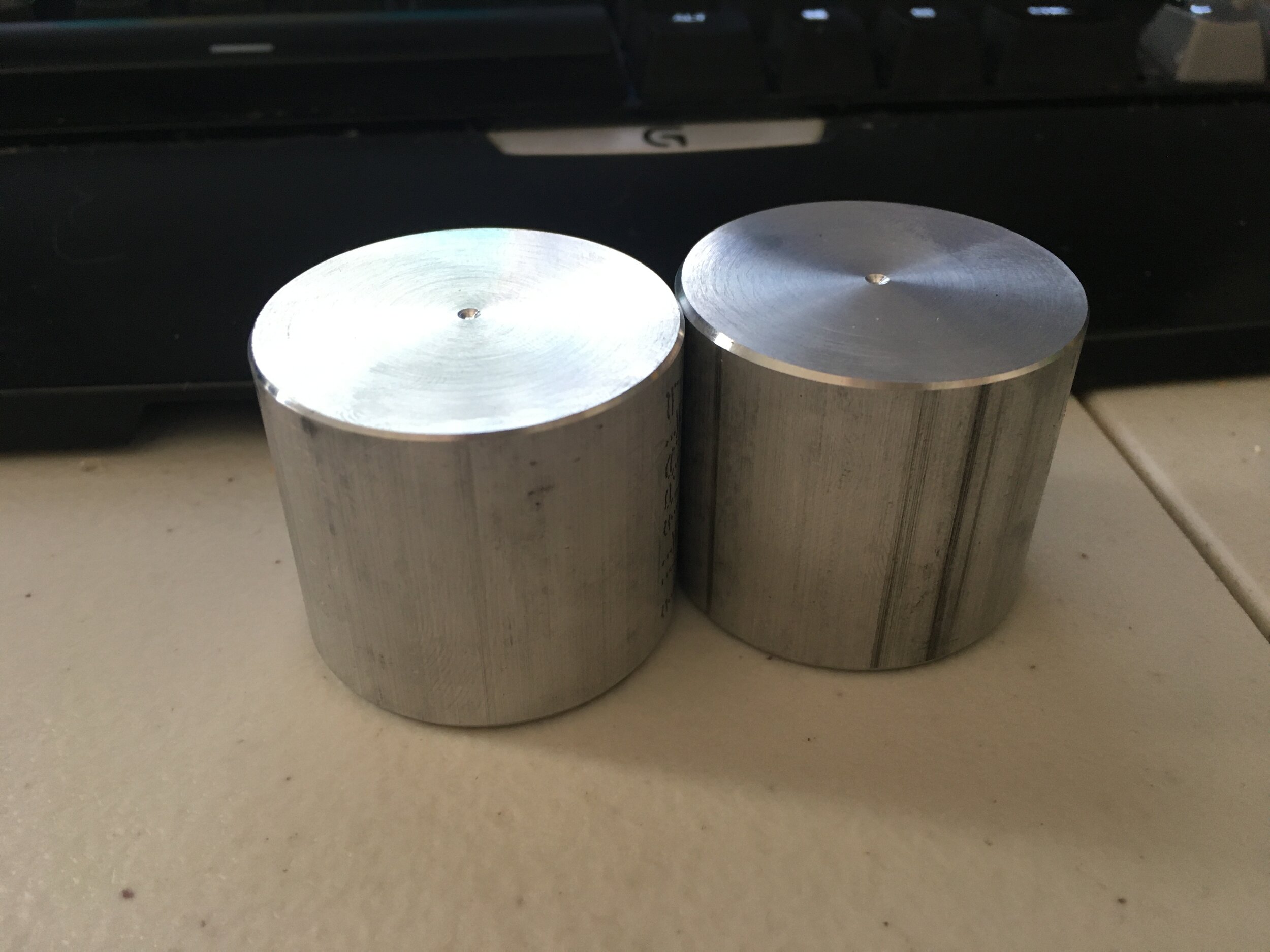
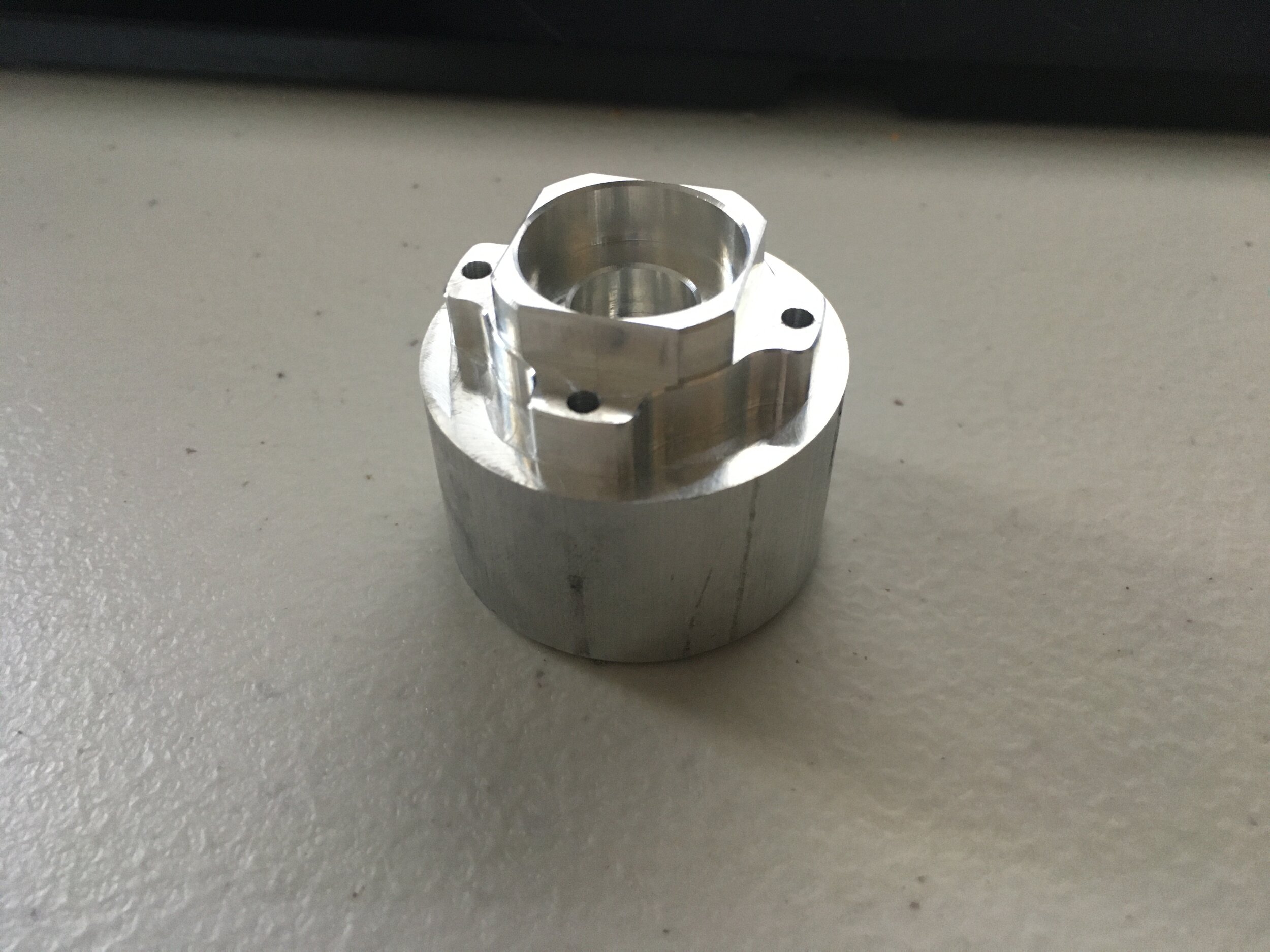
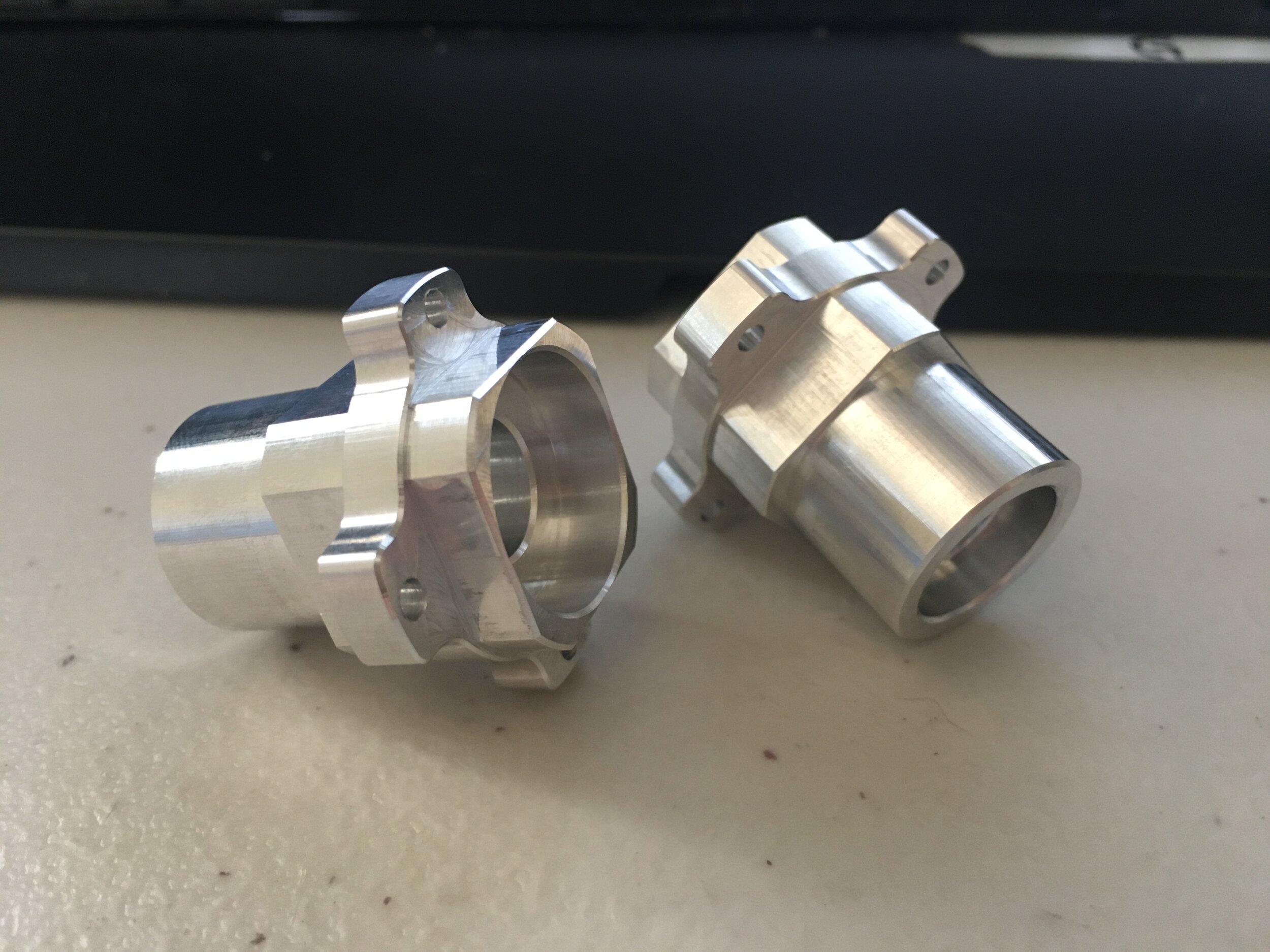
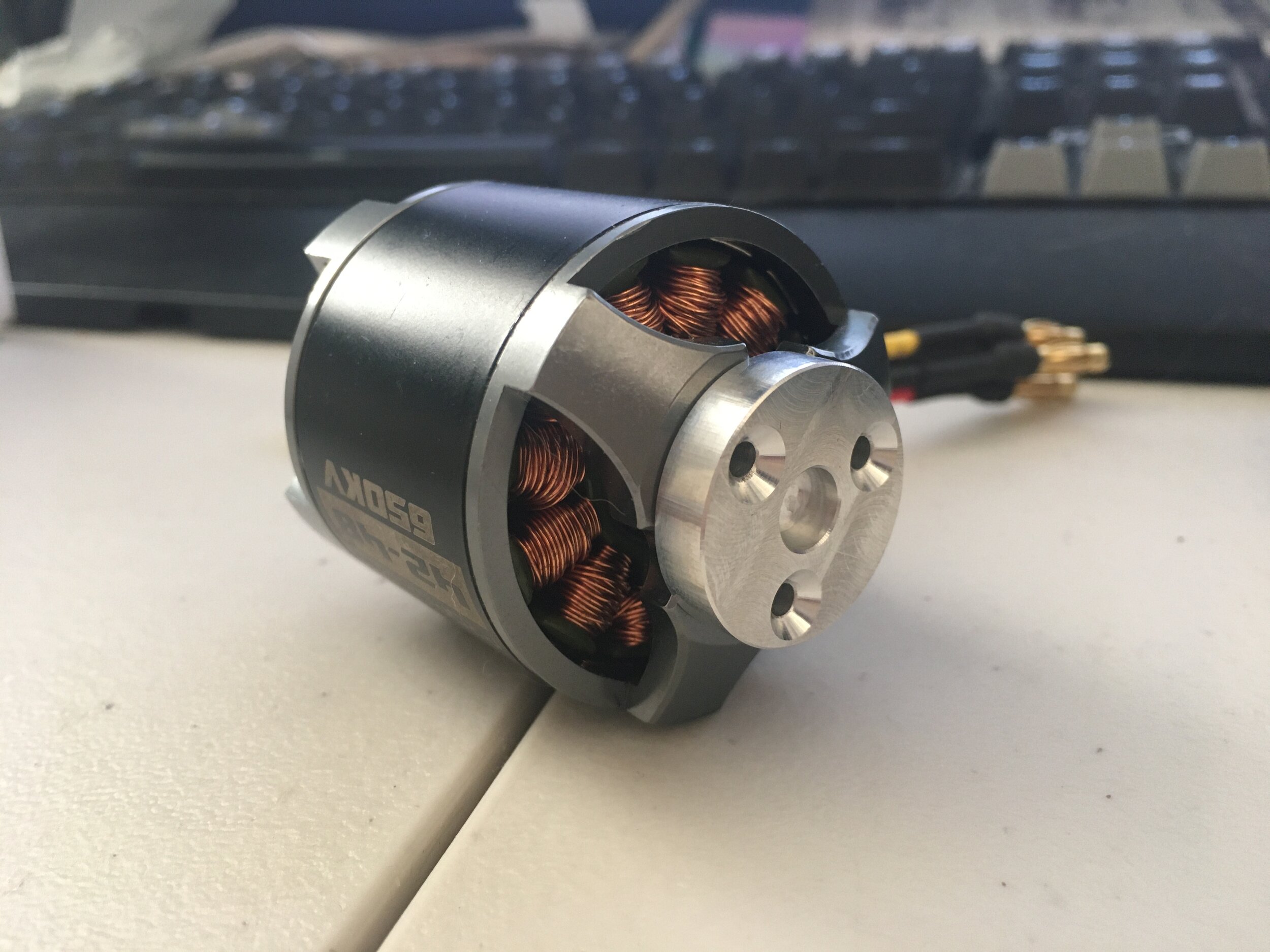
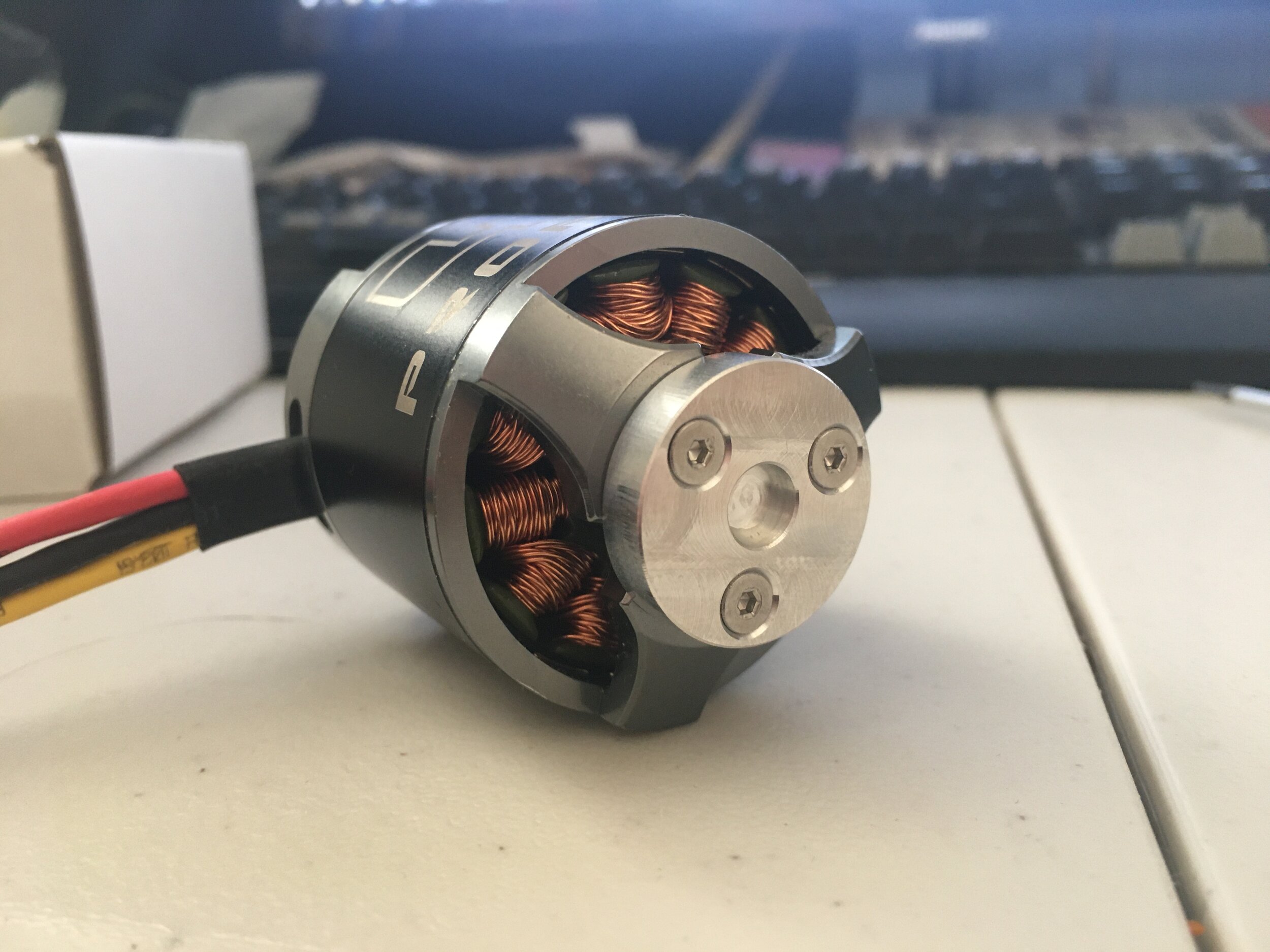
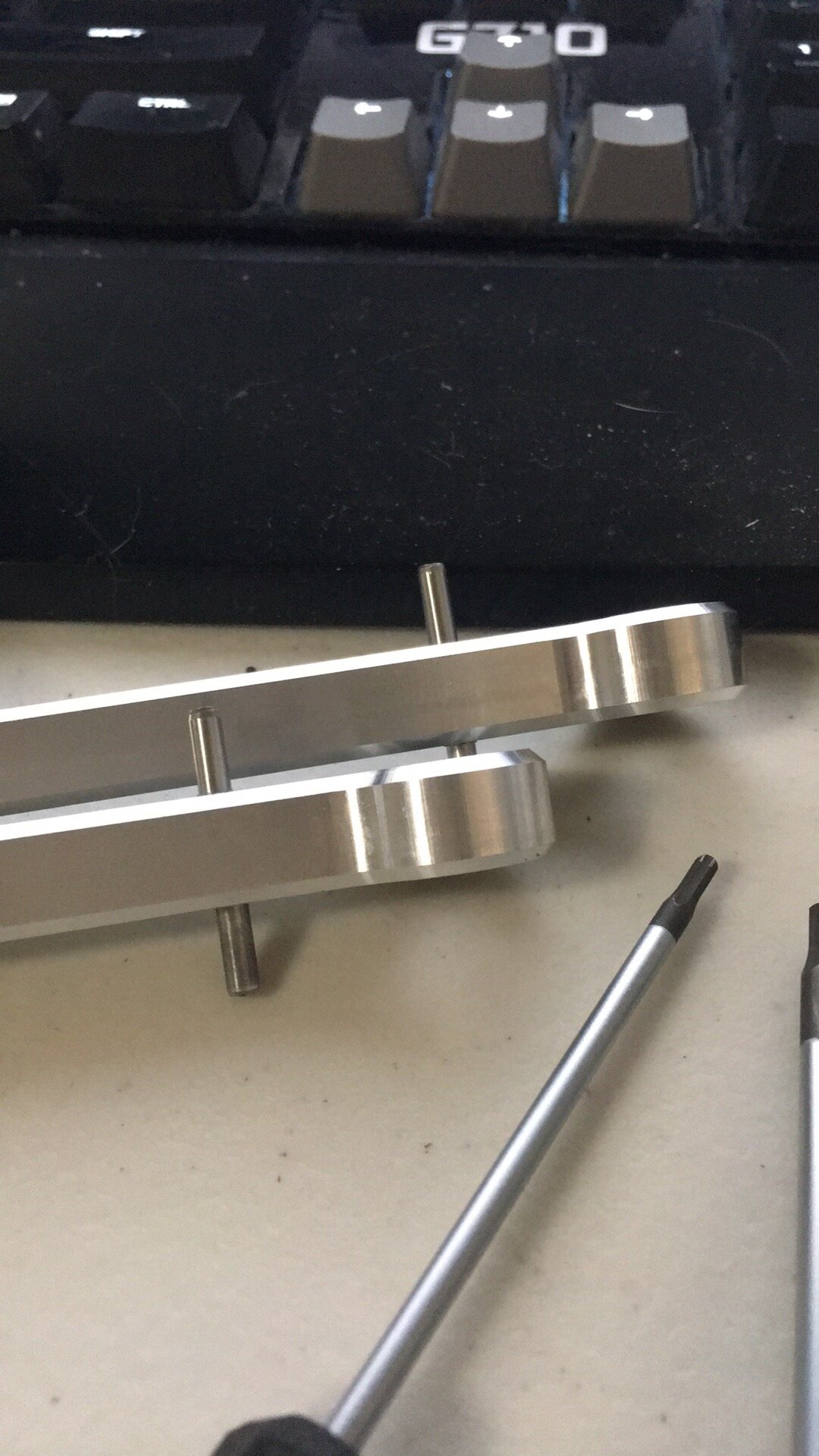
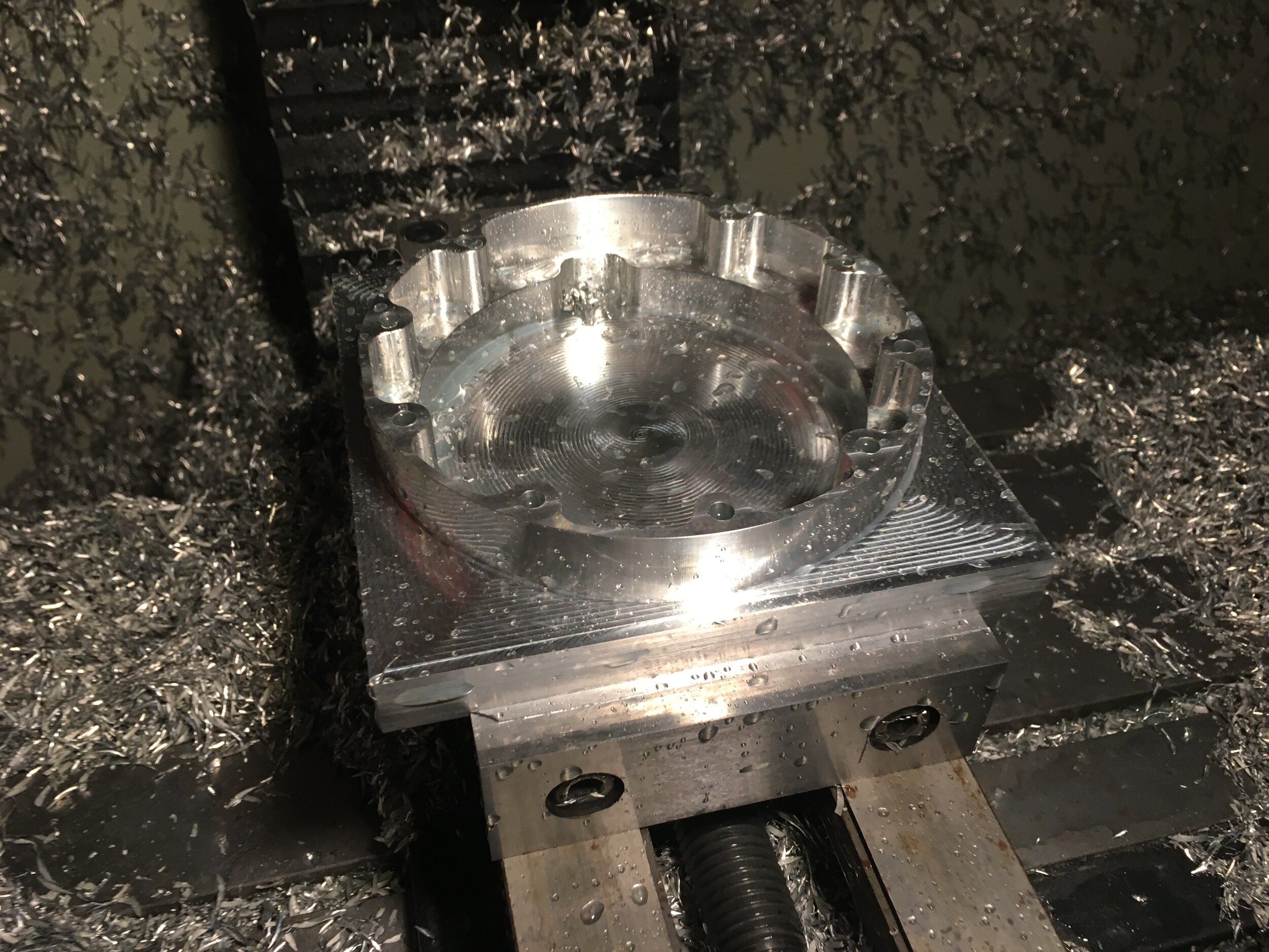
First came the Banebots wheel hubs
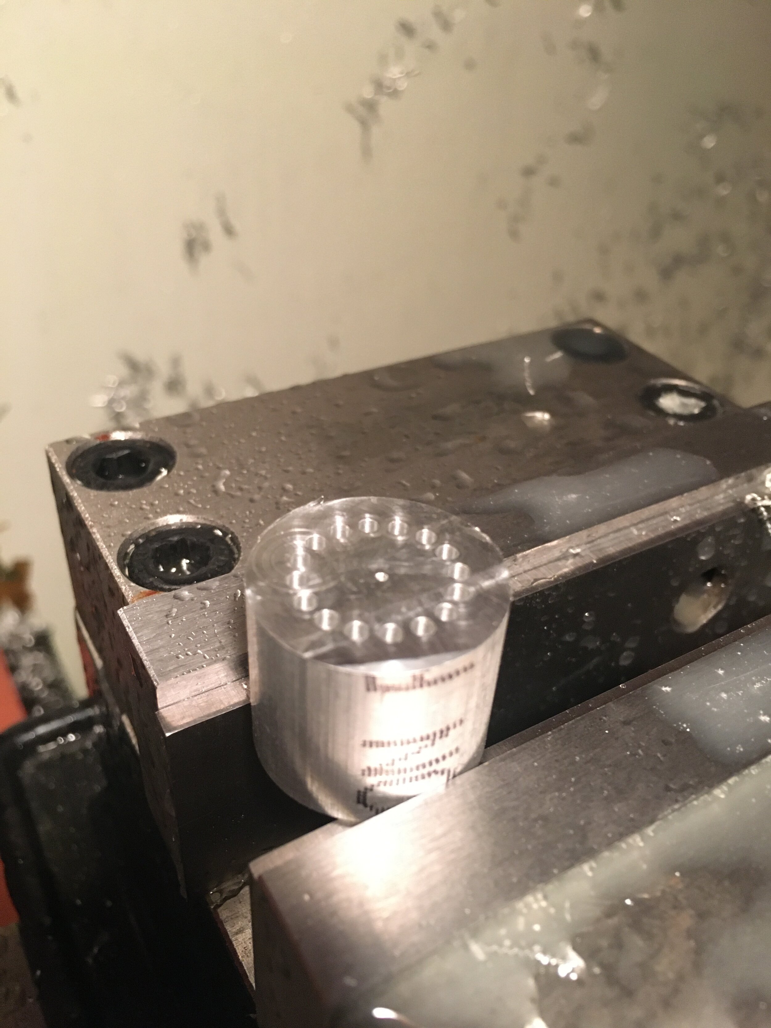
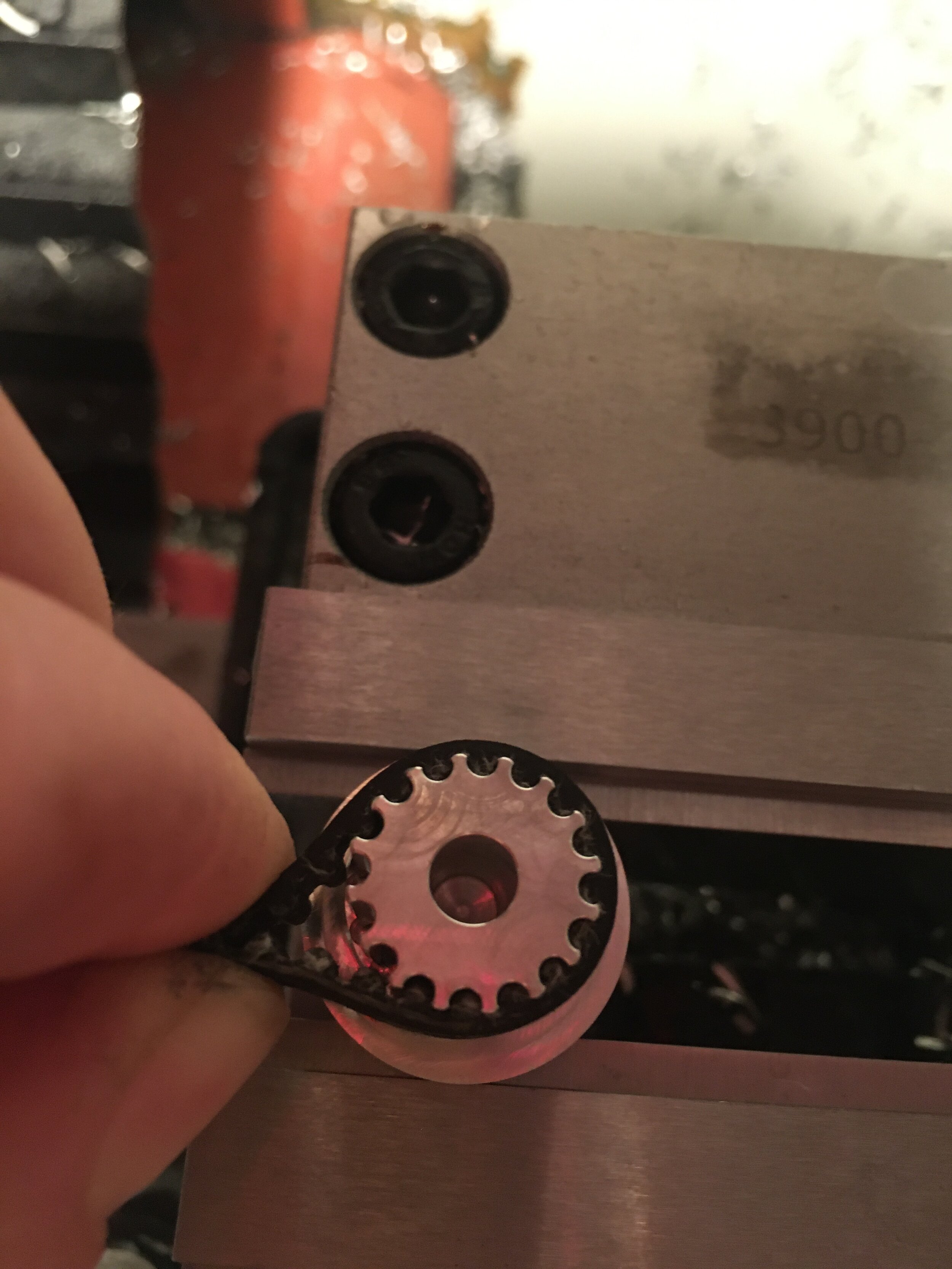
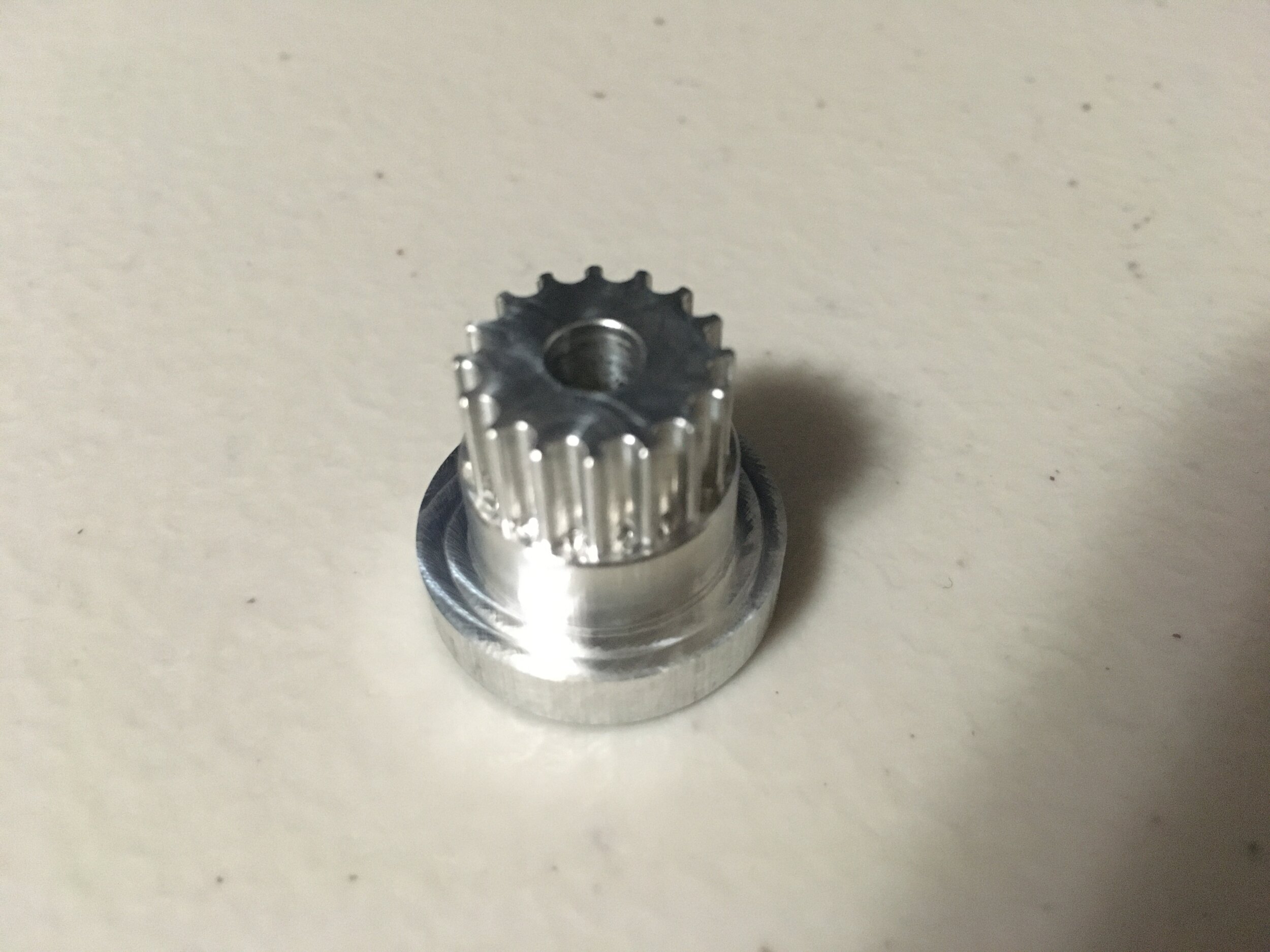
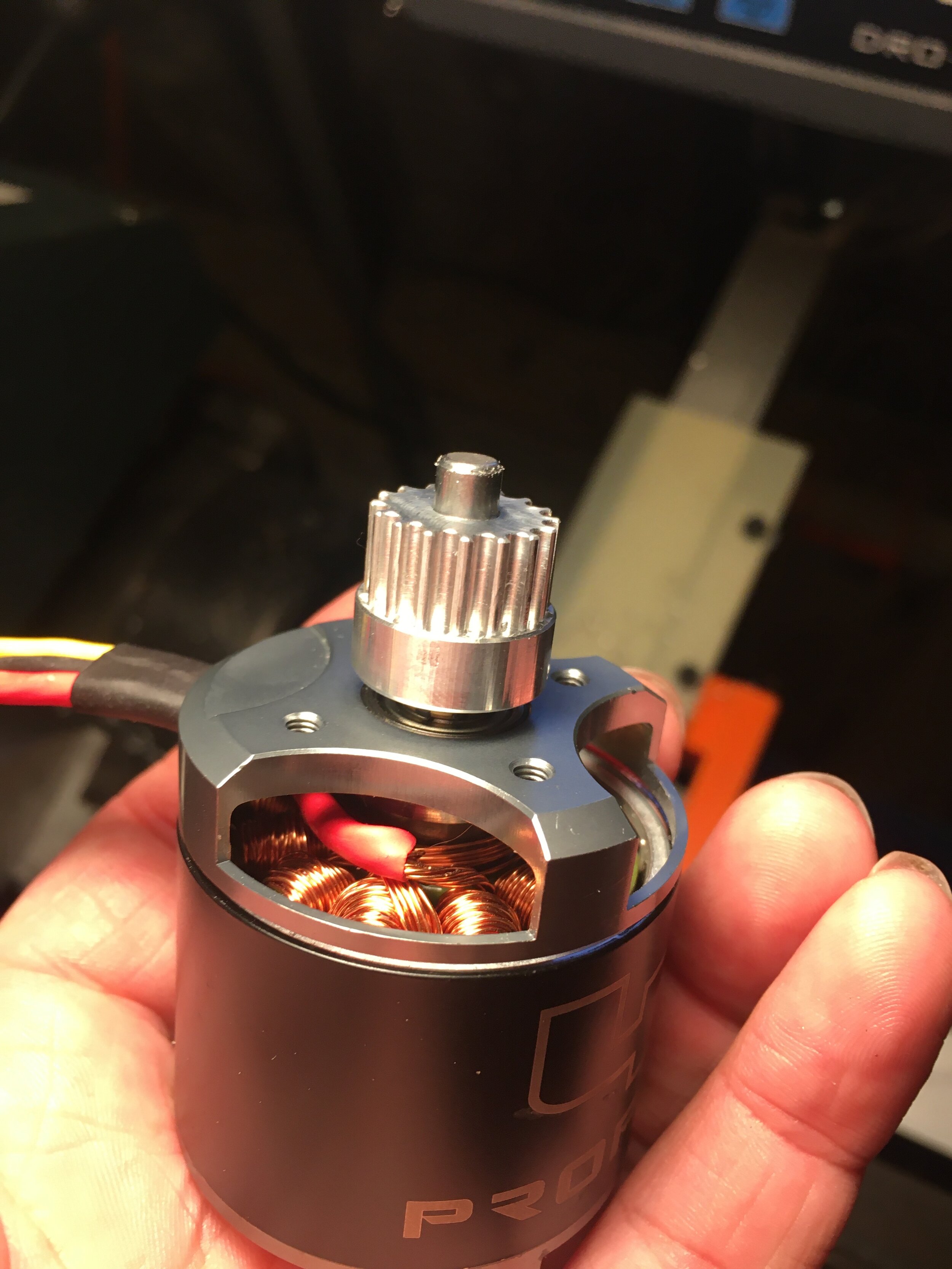
Next came the balance motor timing pulleys (3mm HTD). These were interesting since I didn’t want to use a miniscule endmill. I predrilled the tooth profiles first, and then only finished with an 1/8” endmill. Worked great as you can see!
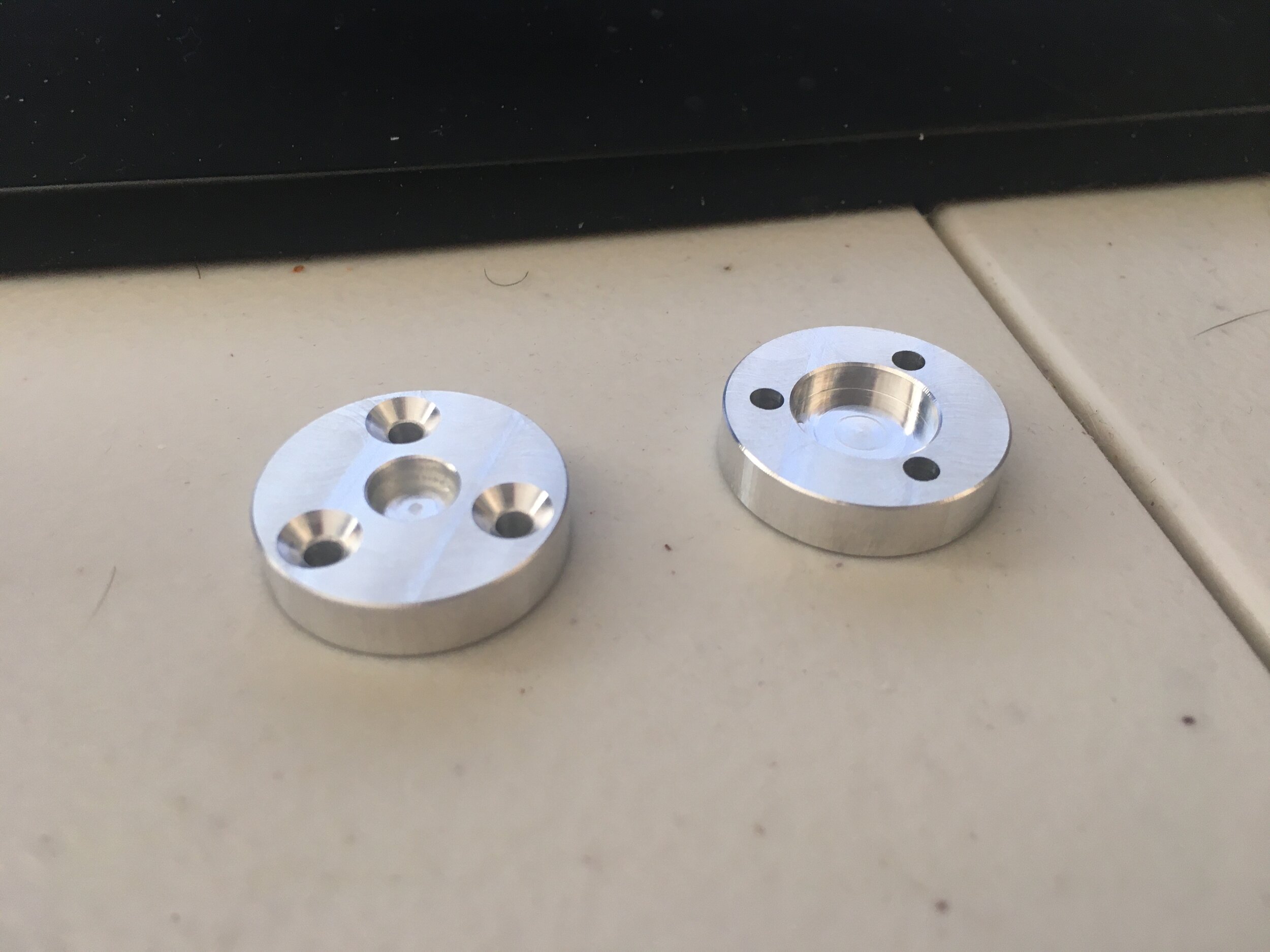
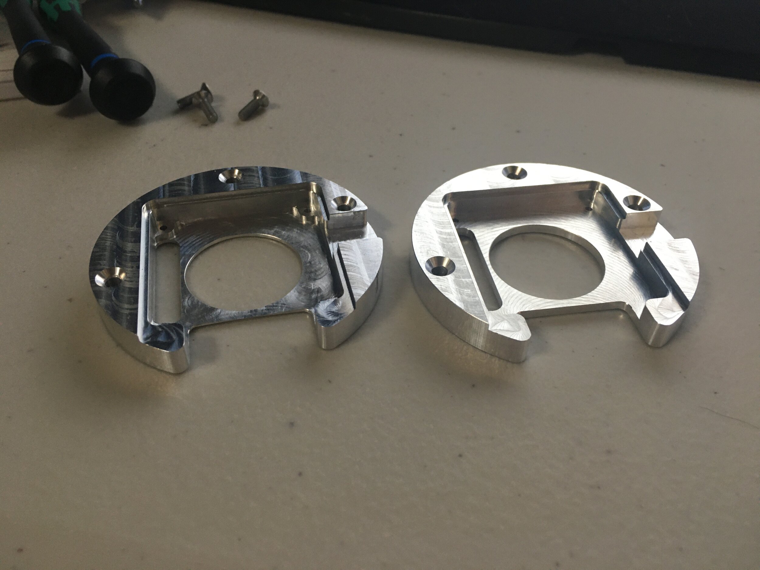
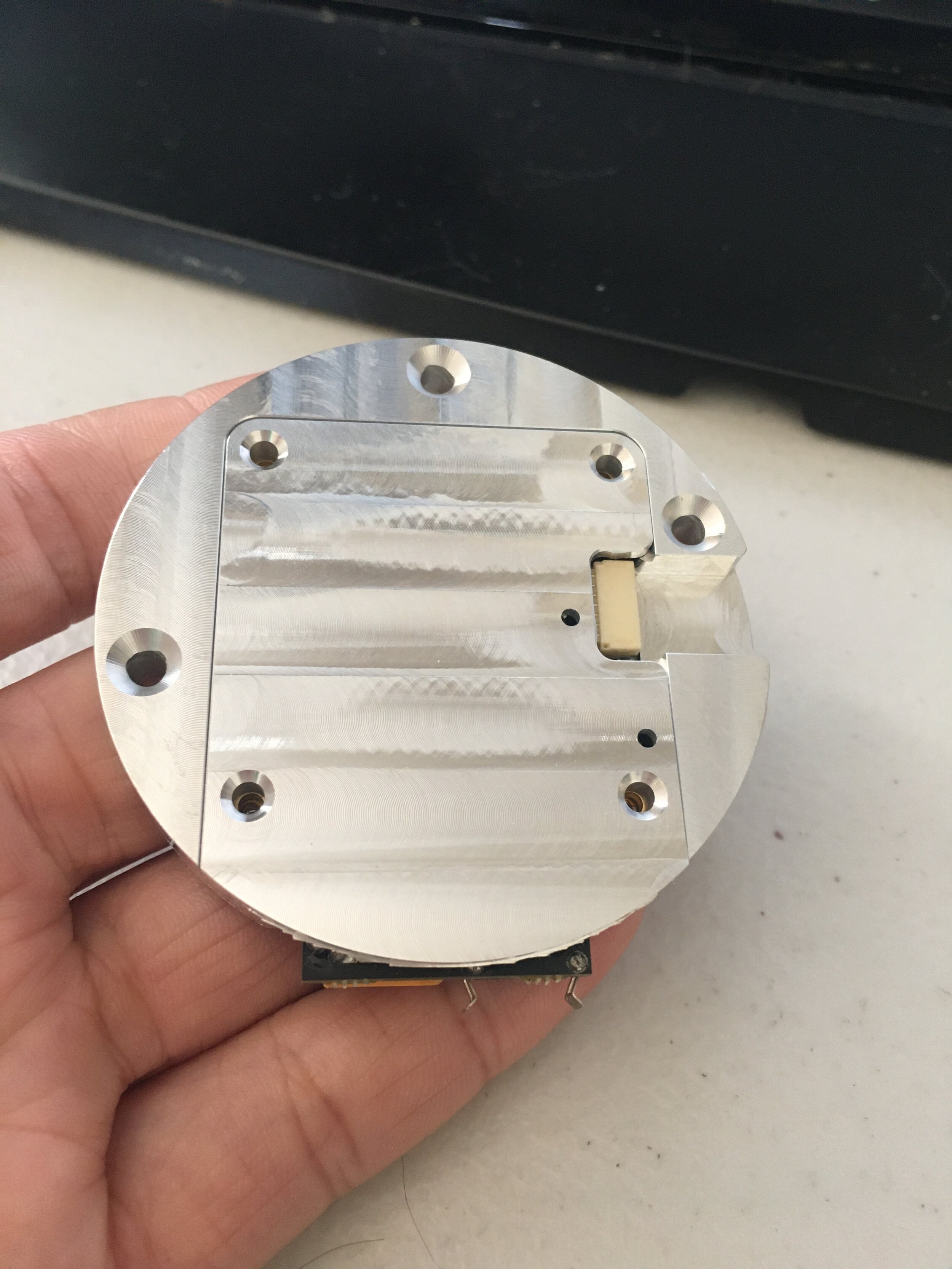
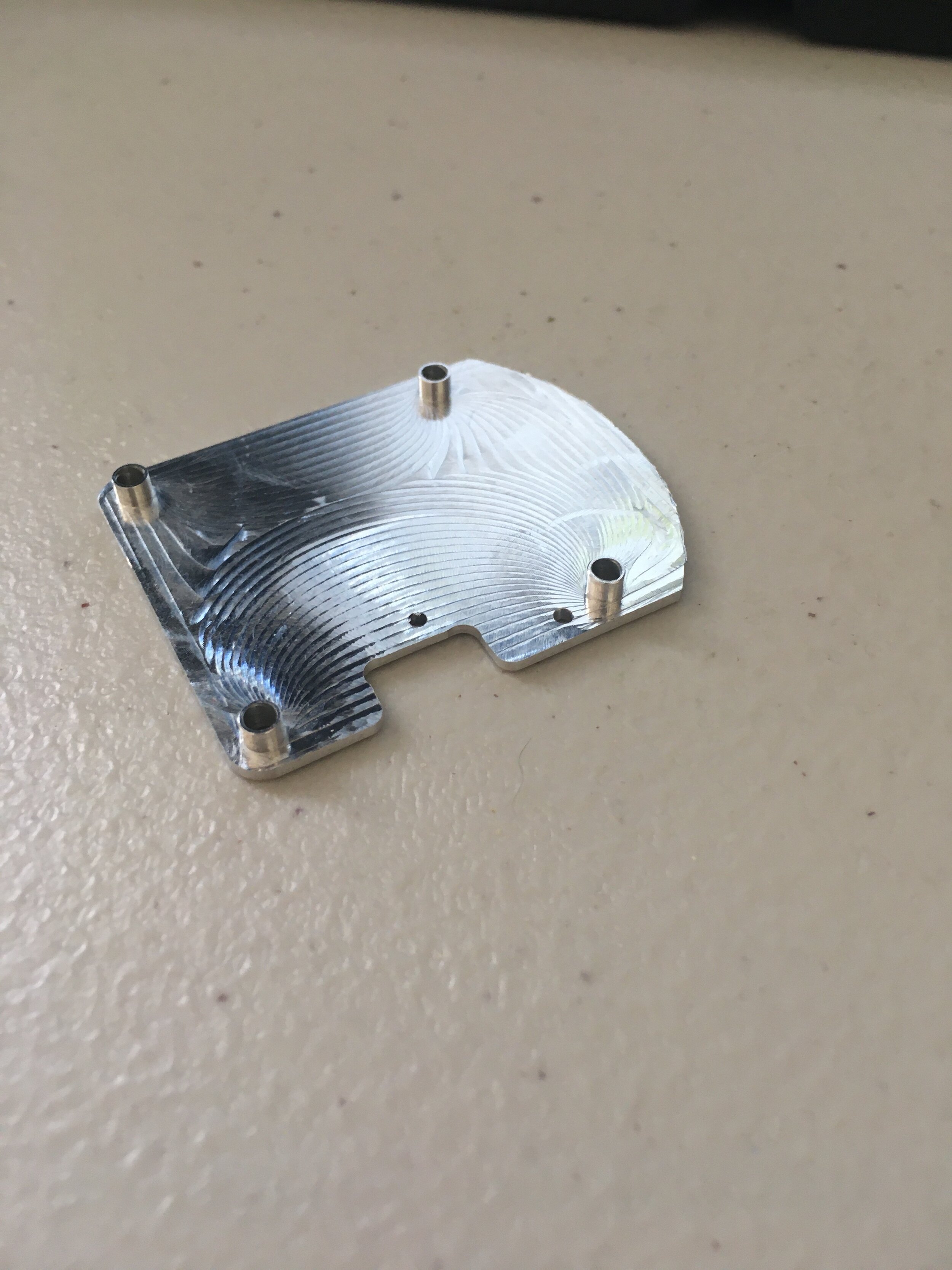
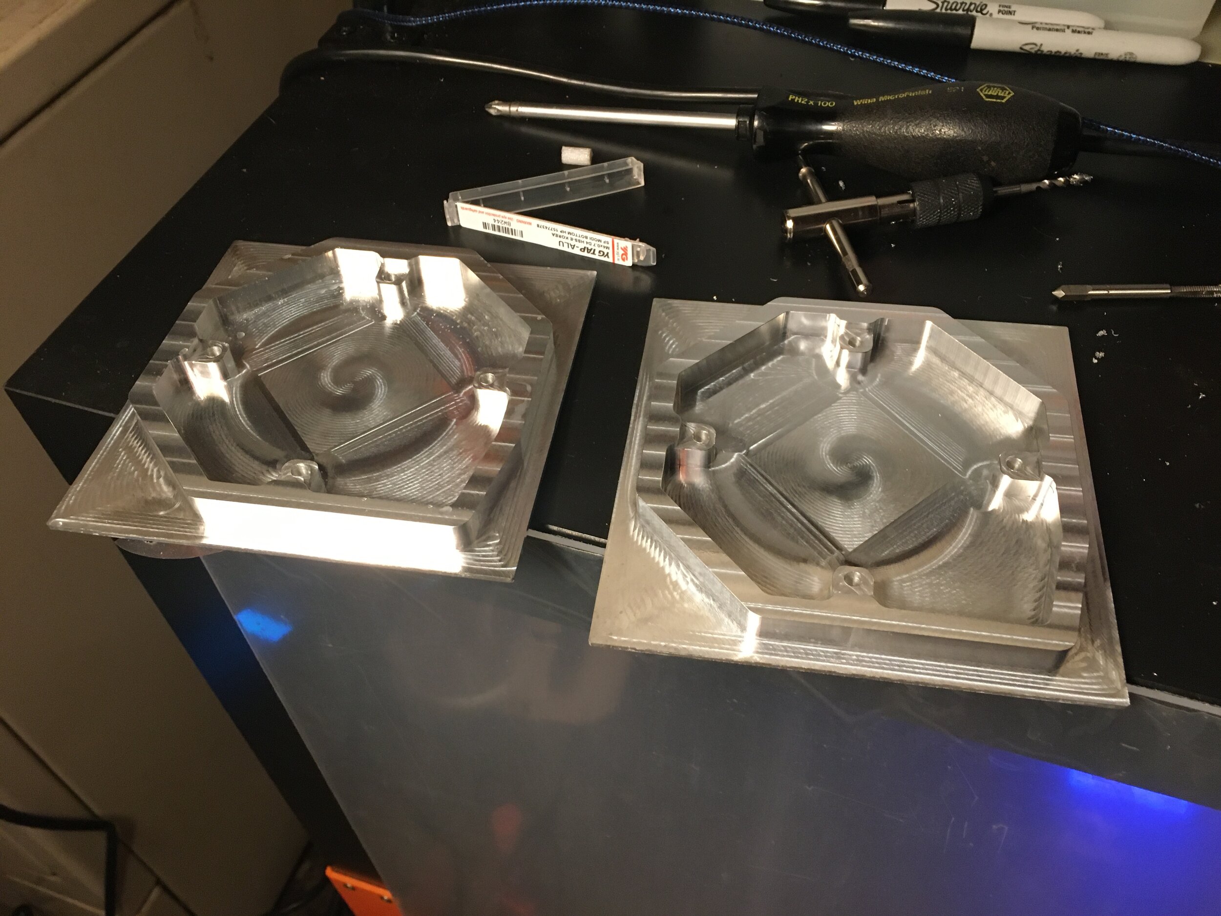
Next came the encoder magnet holders which I did out of 6061 just for pride purposes
By this point my big ebay order of 6061 had come in for all the leg links!
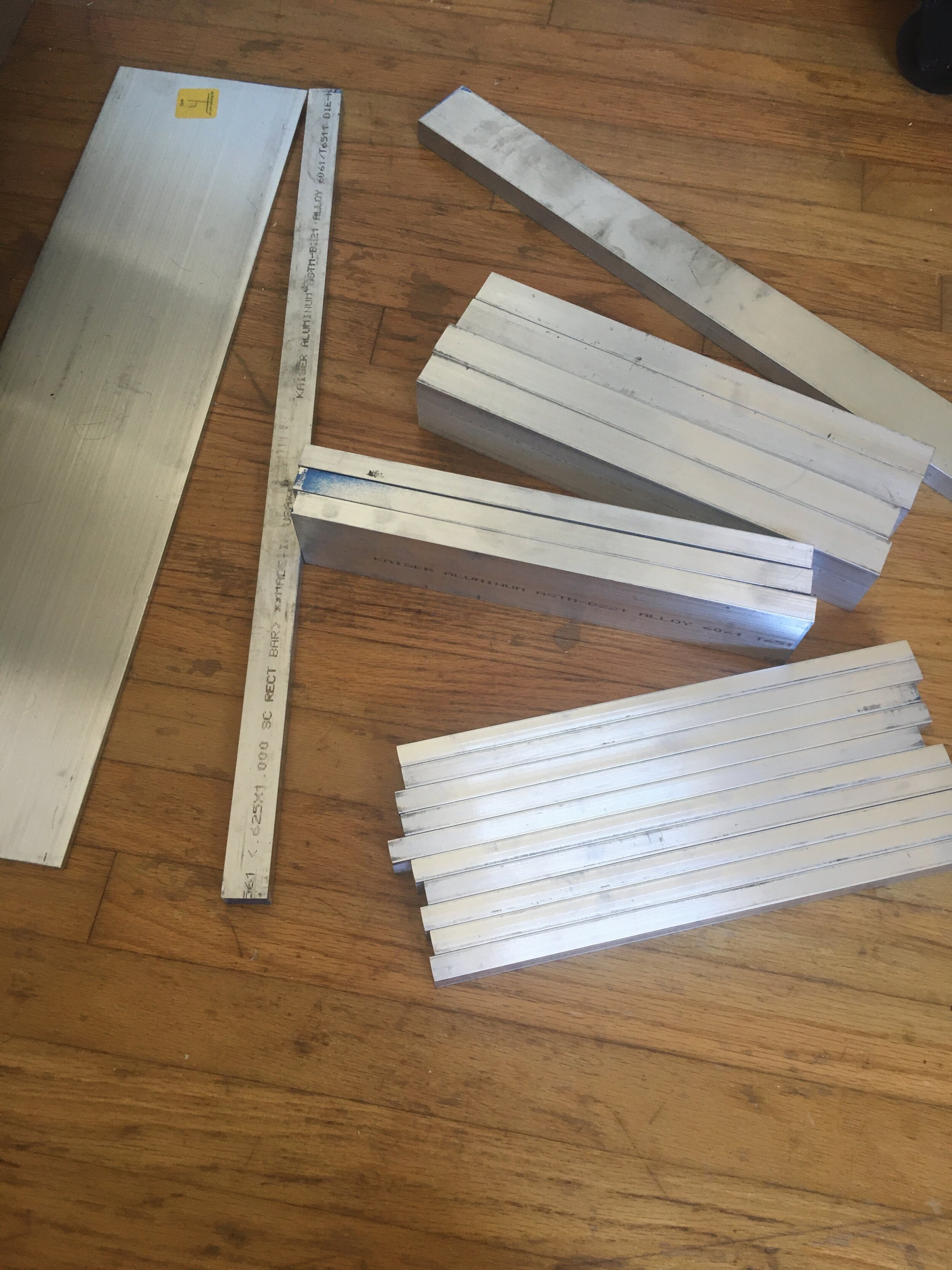
I also knew that with my machining style I would need a LOT of softjaws so I made a bunch (one set/type of part since I could use top and bottom of the softjaws, but the leg parts are mirrored across the robot). I also had to center the vise carefully because I knew I had ~0.25” of travel clearance on the x axis for some of my longer parts.
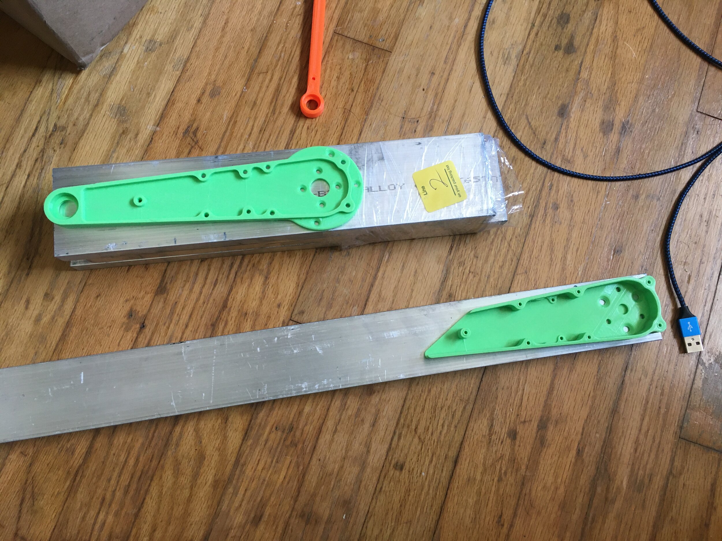
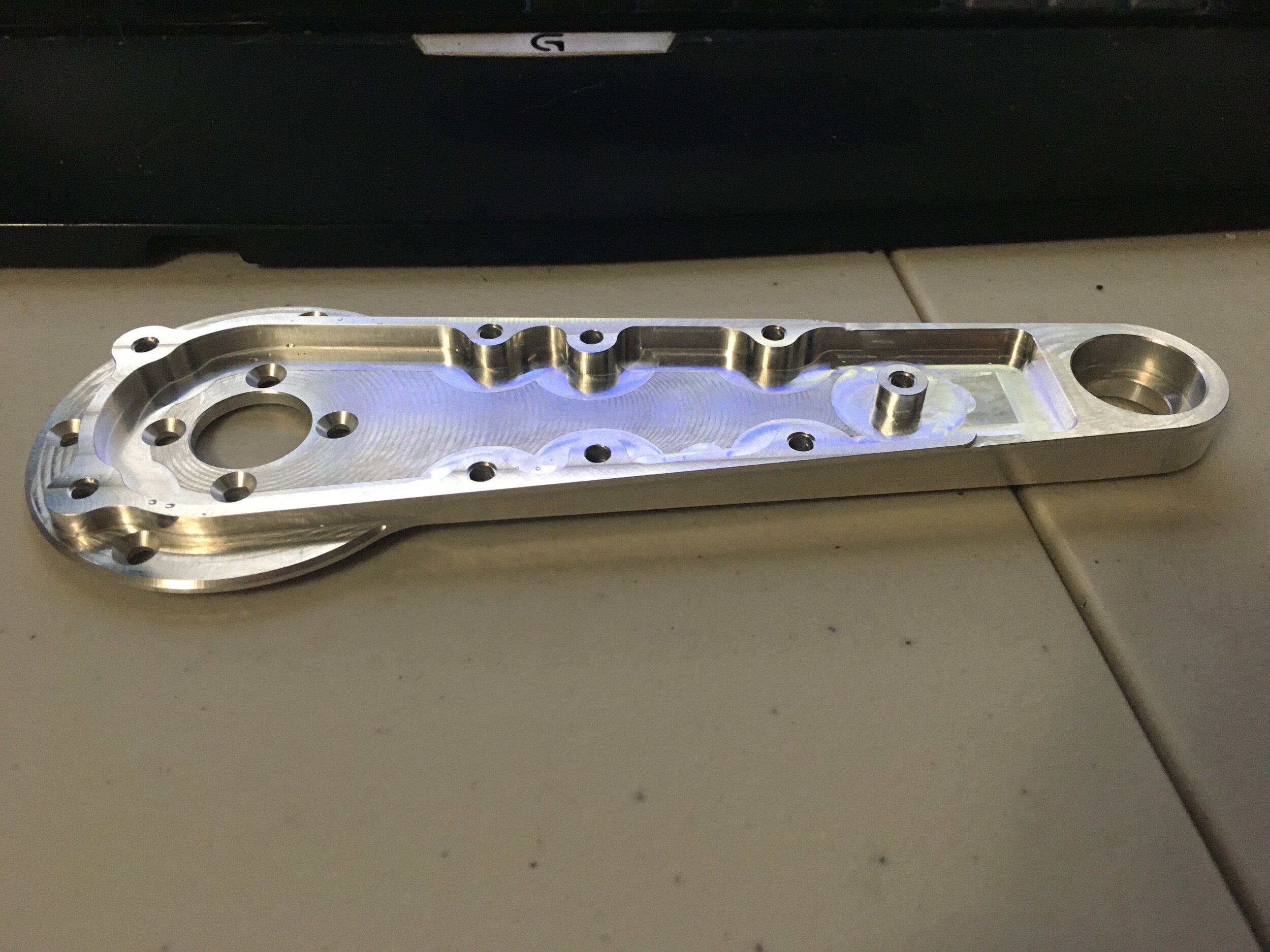
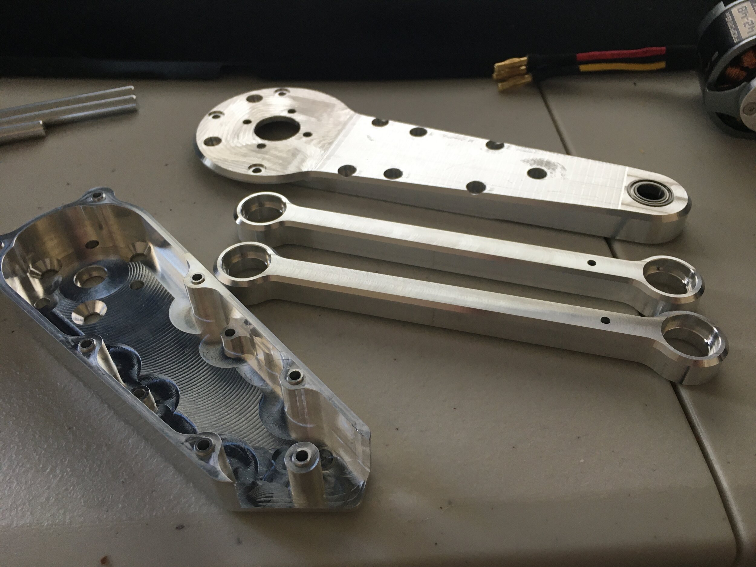
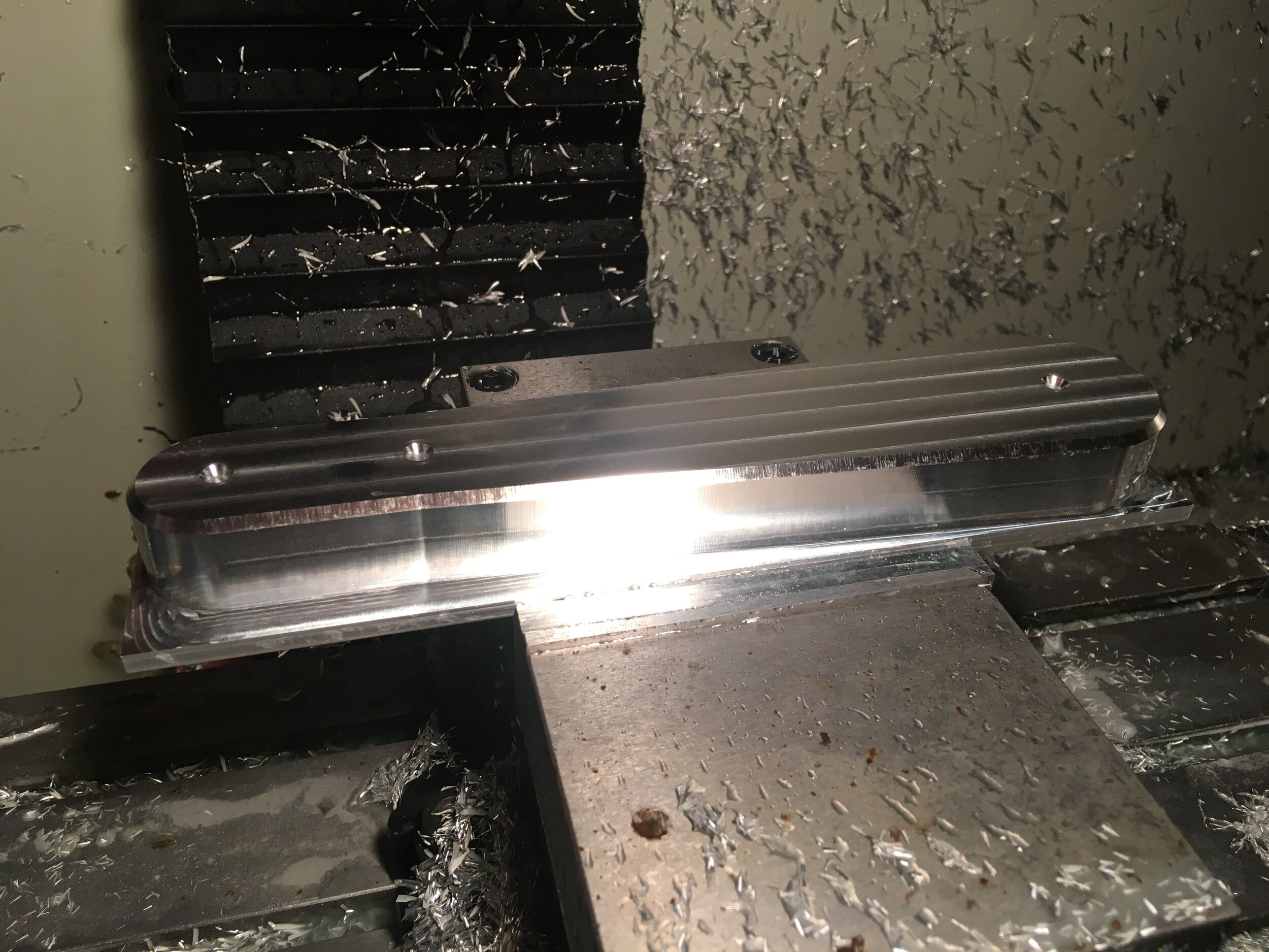
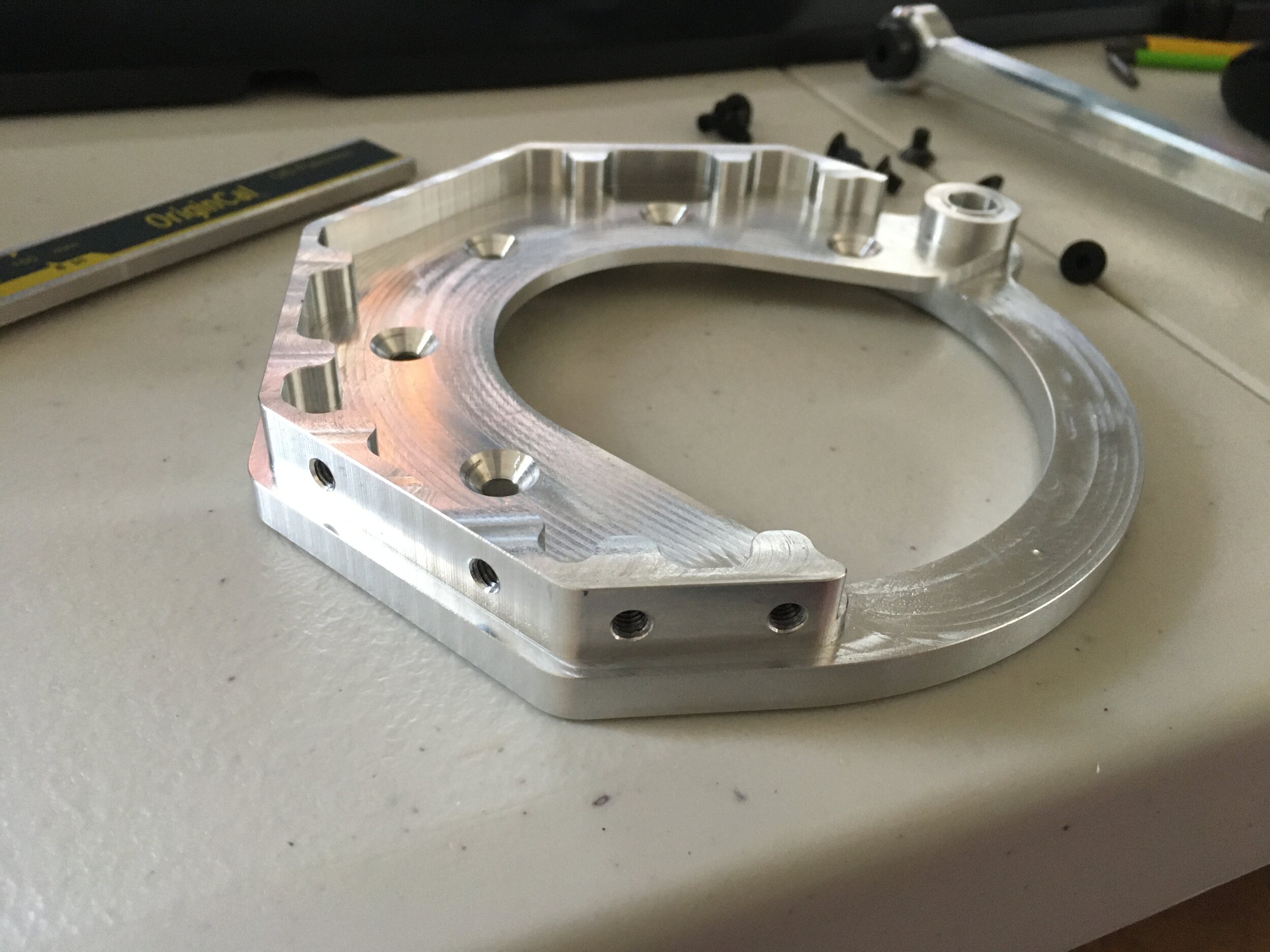
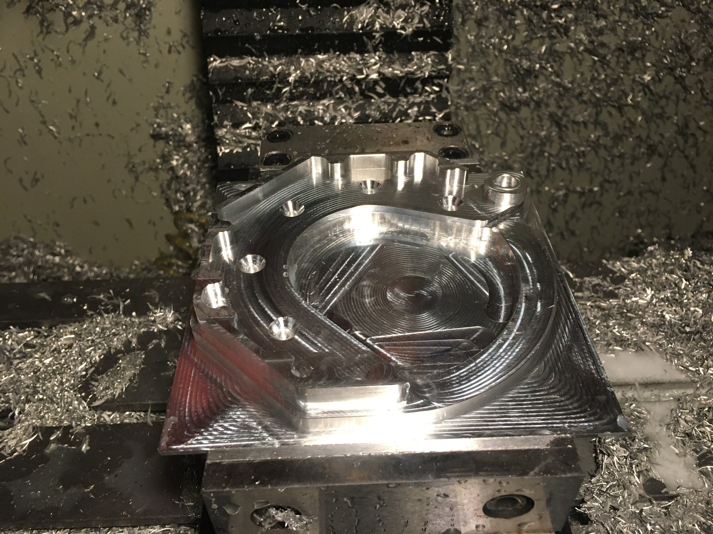
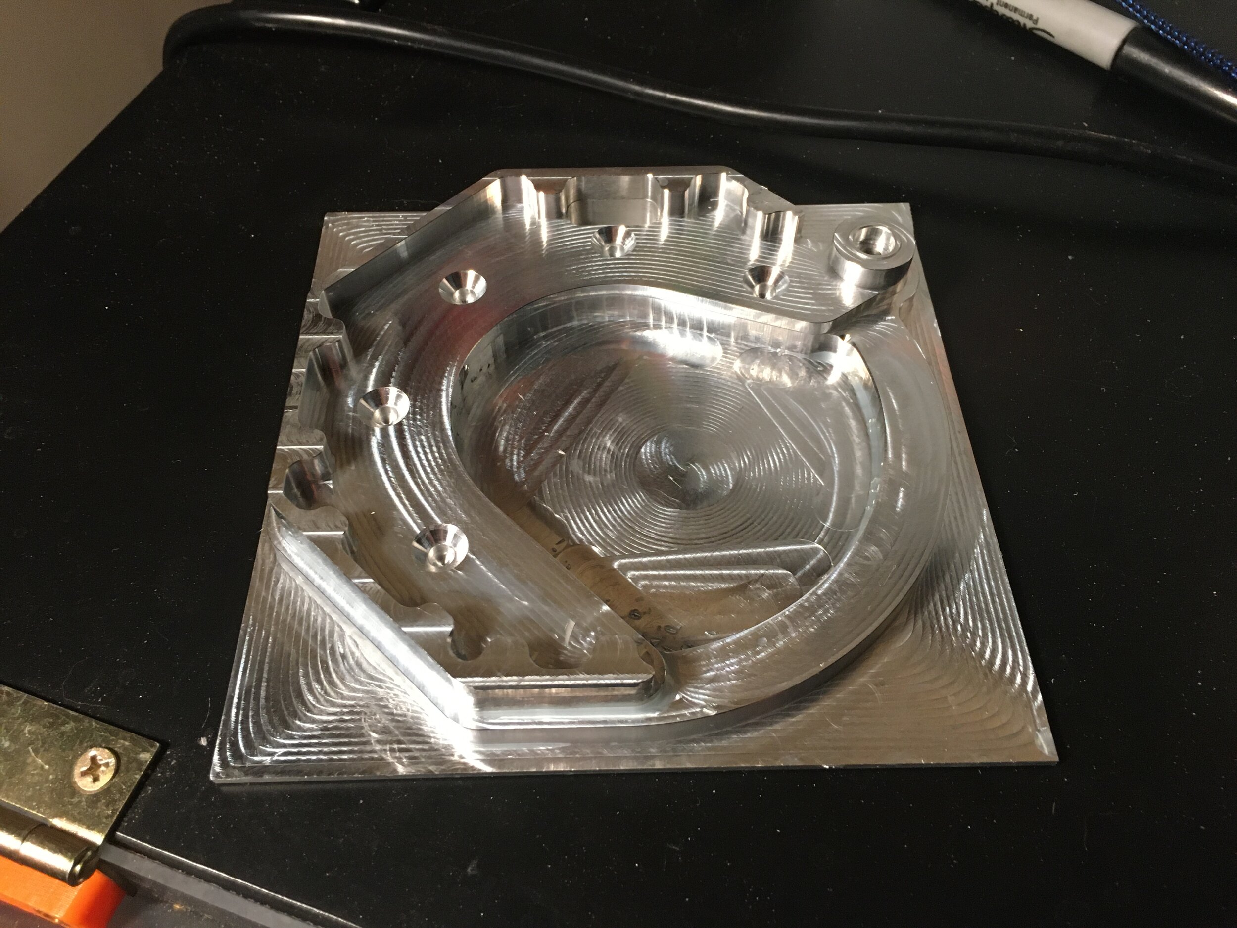
Next came one of the upper leg halves. This was one of the few parts with 3d milling. I found the parallel operation in HSMWorks left a good finish
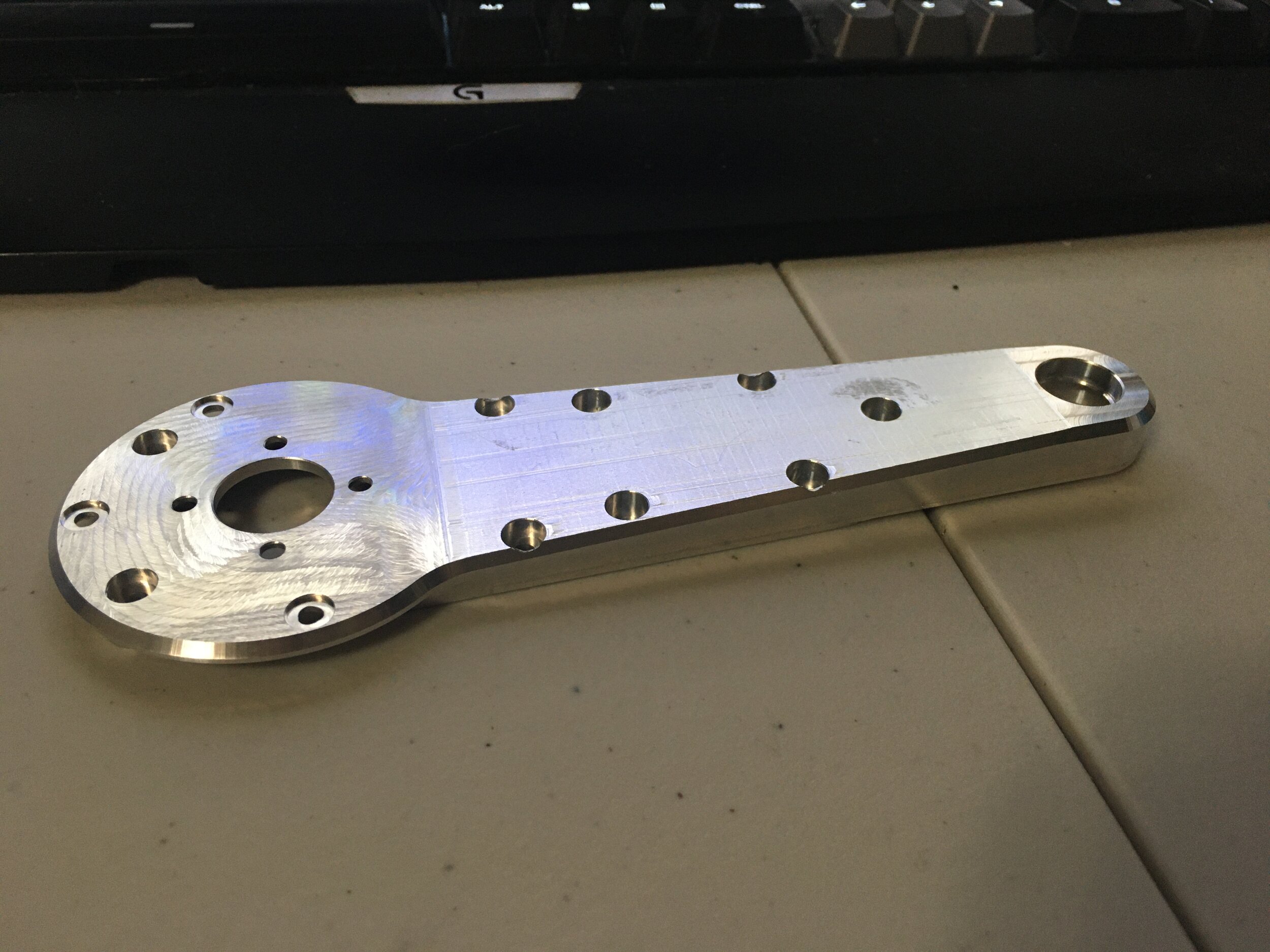
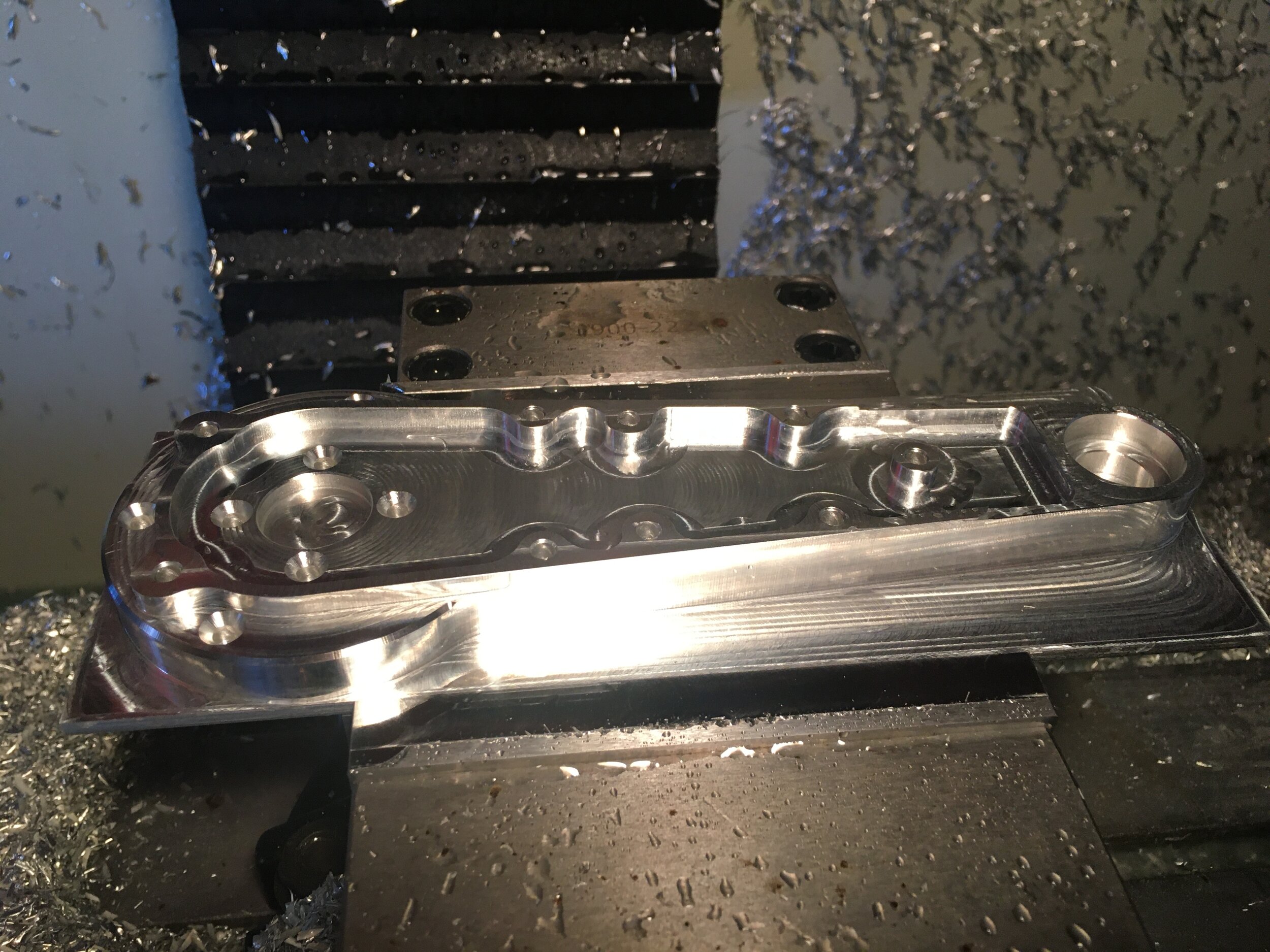
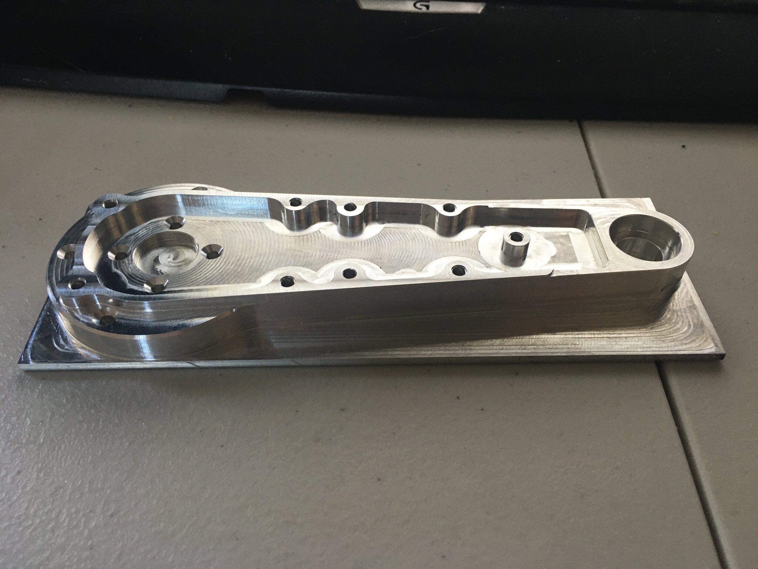
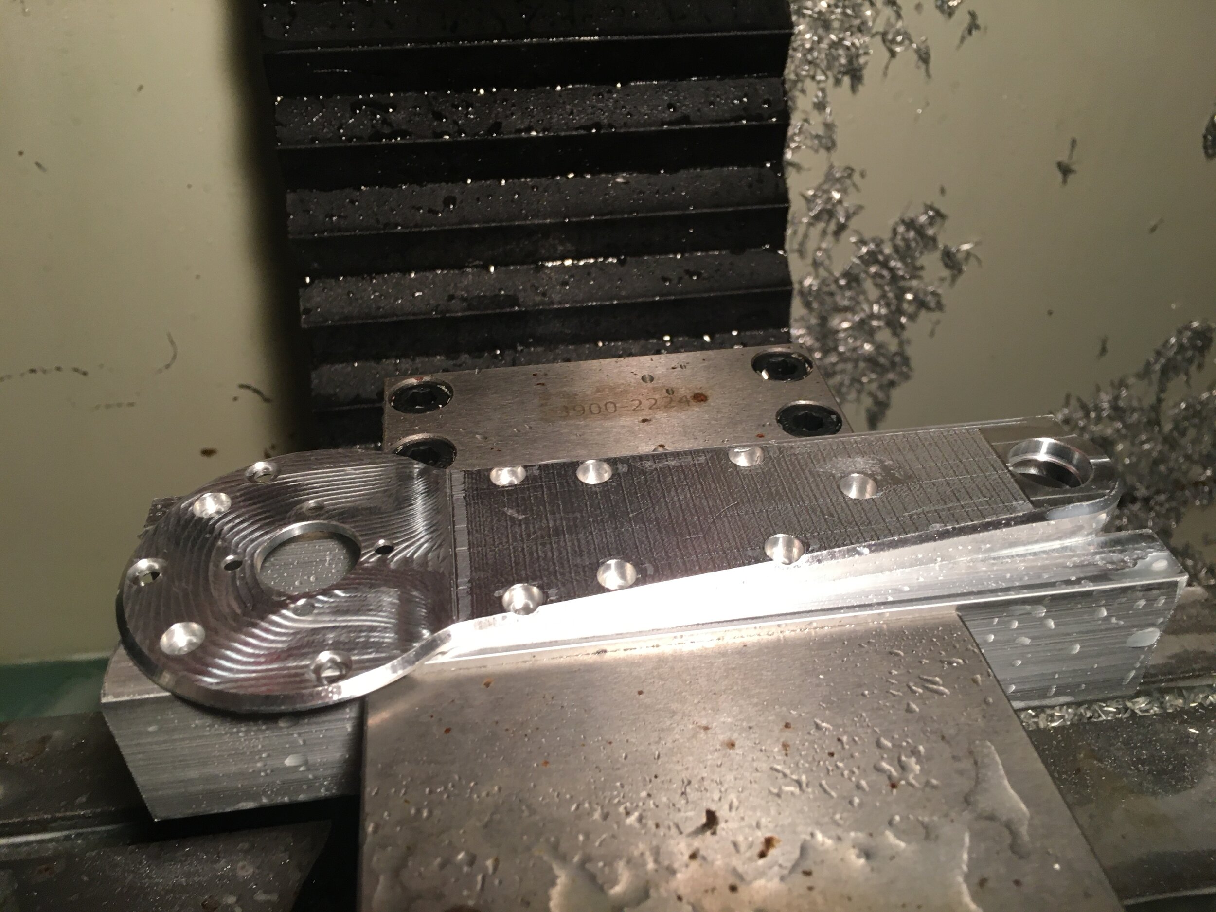
Next came the other half of the upper leg
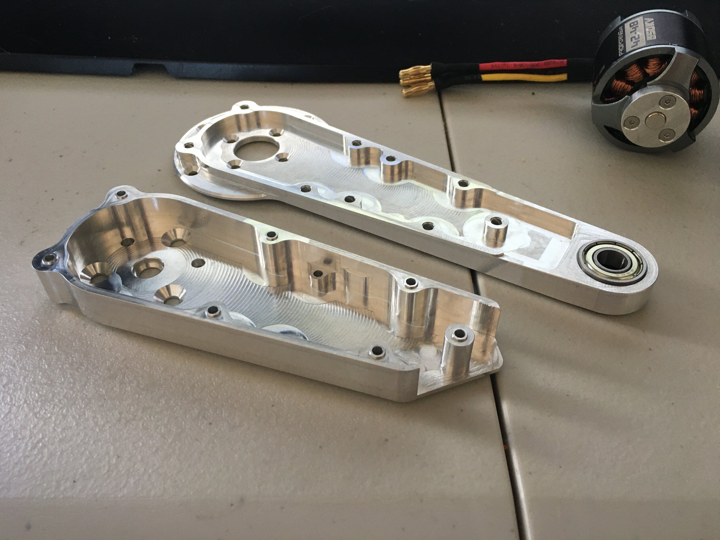
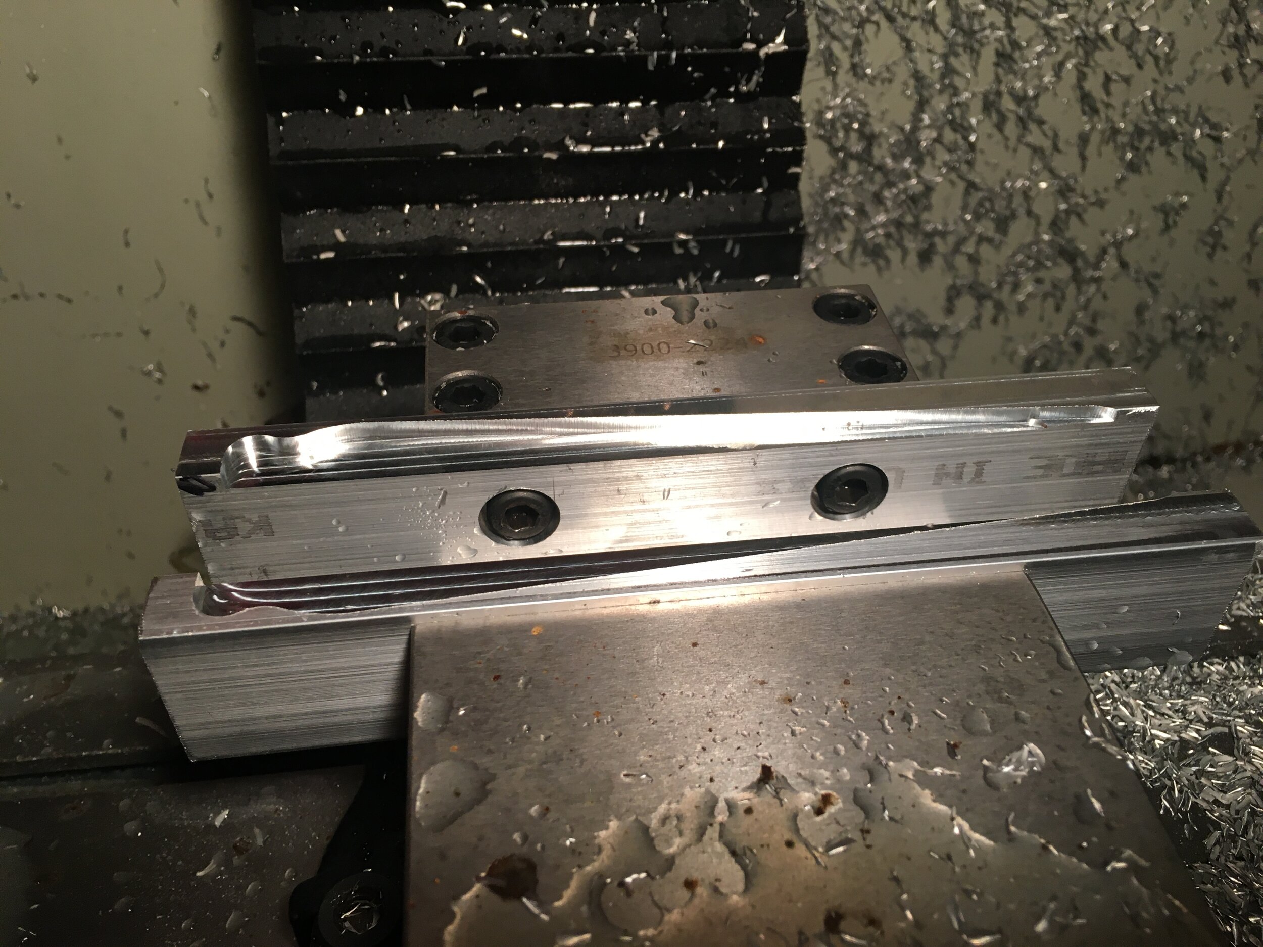
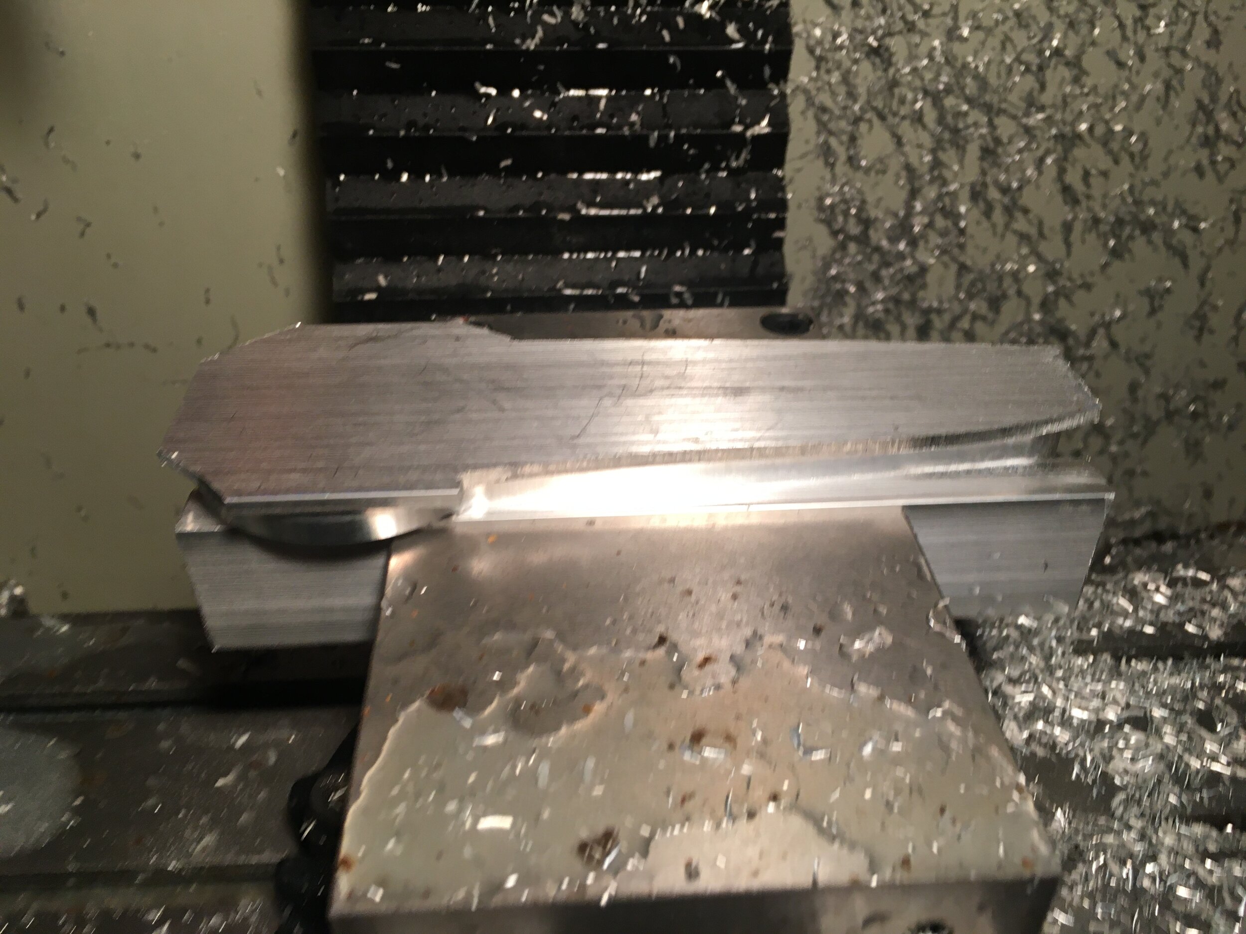
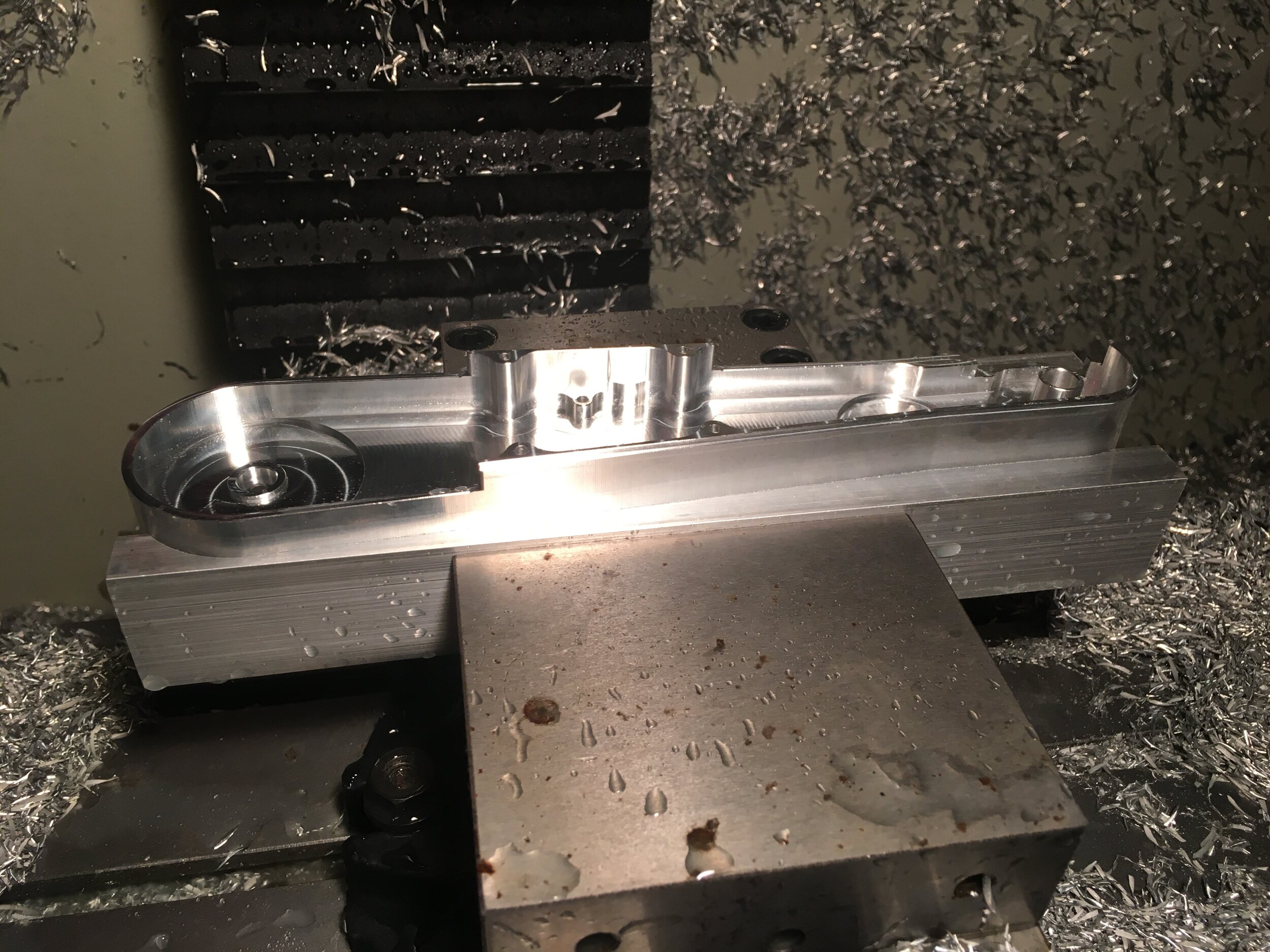
These parts went well so I made the mirrors of them, as well as the 4 bar links. Note: the picture below doesn’t show the mirrors.
One tricky operation I needed to do in a few parts was drilling a tapped hole for the setscrew that tensions the belts. I printed an angle block and used it as a zero reference.

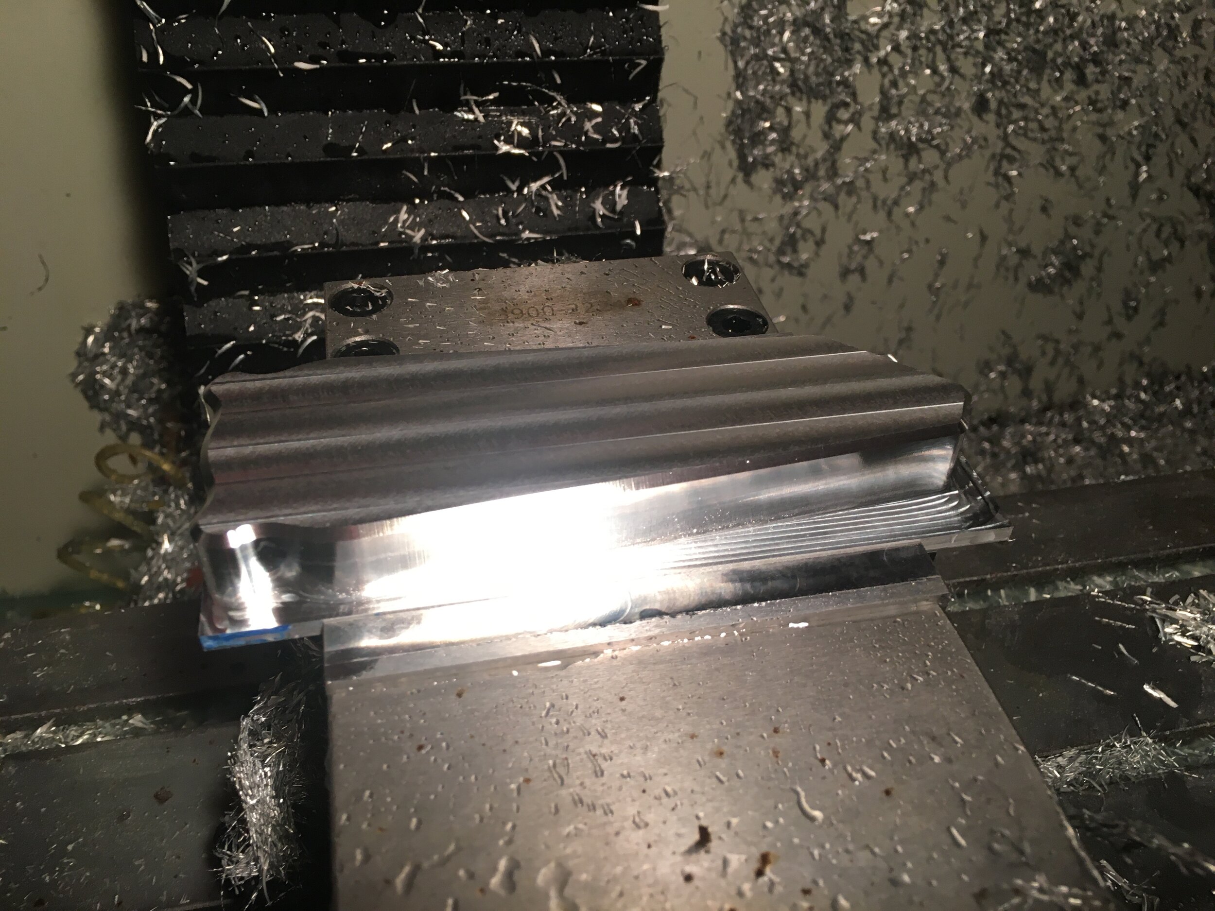
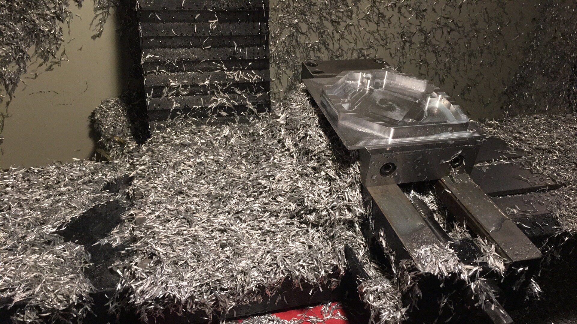
Next came the trickiest parts: the lower legs. These barely fit on the mill and so I had to parse the gcode manually to make sure I didn’t overtravel. Tricks like facing along the y-axis instead of x also helped.
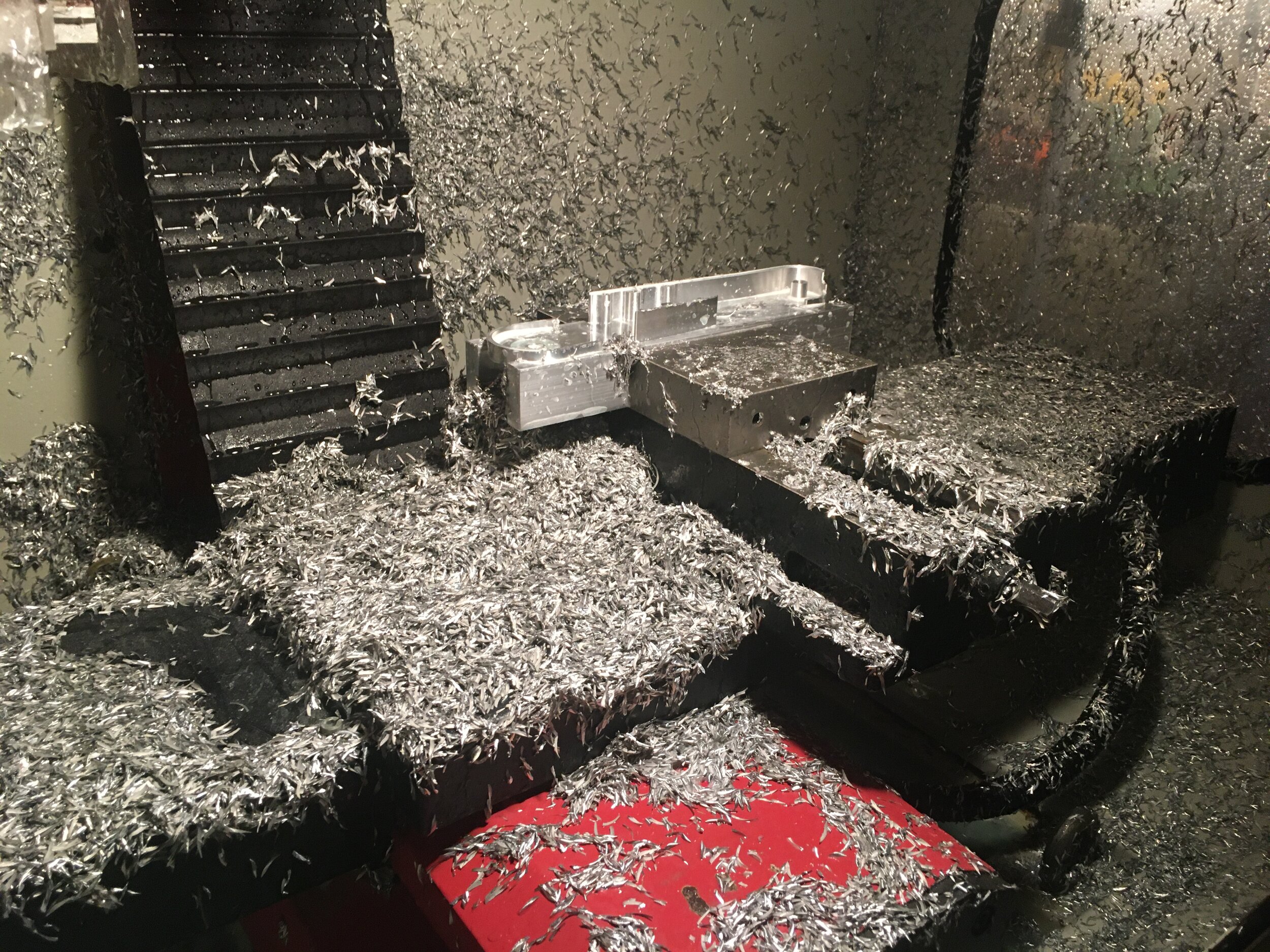

This was definitely the most chips I’d made in a mill this small!

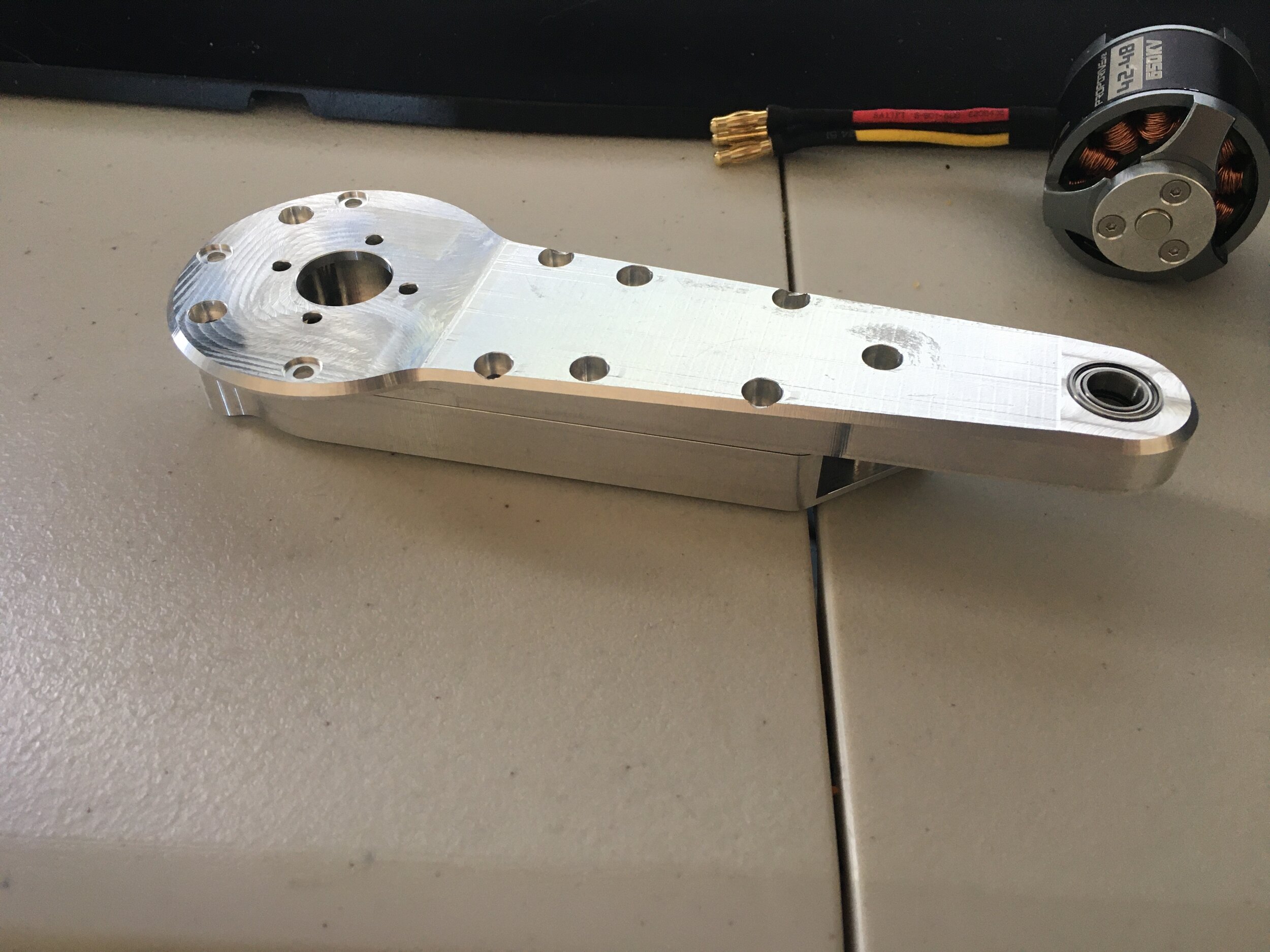
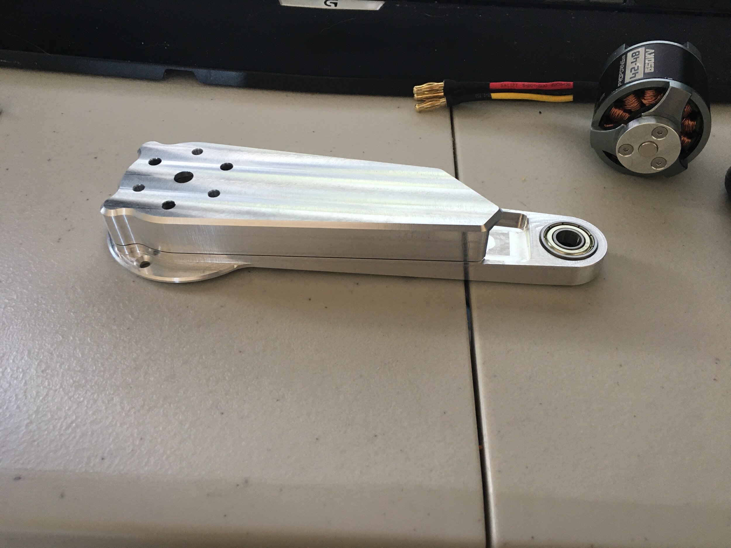
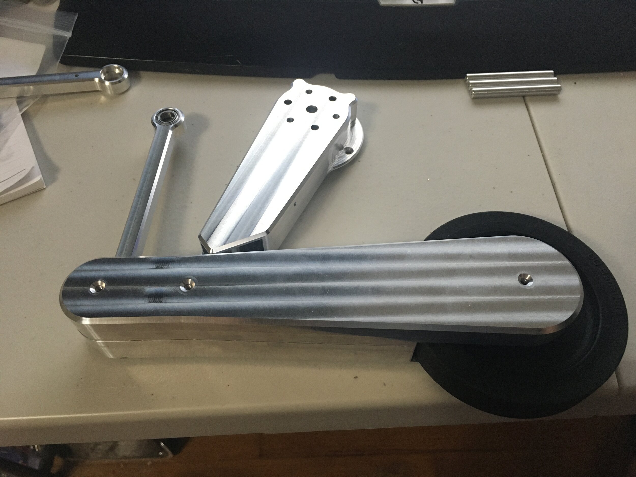
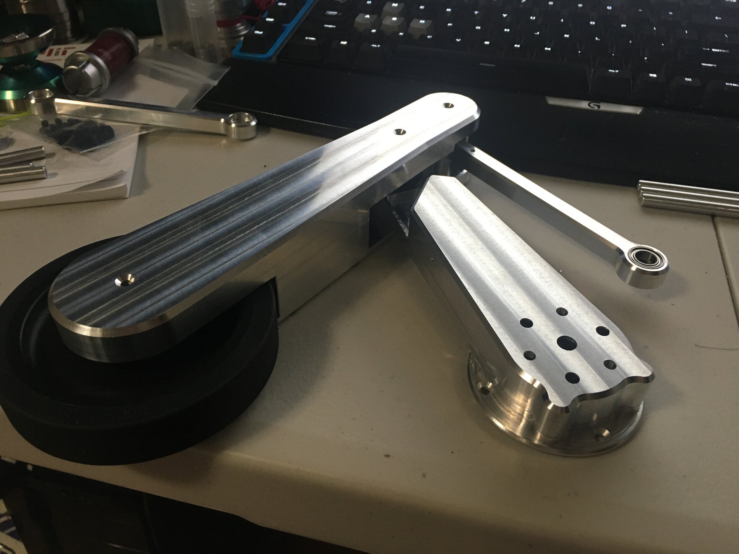
And I was able to assemble the first leg!
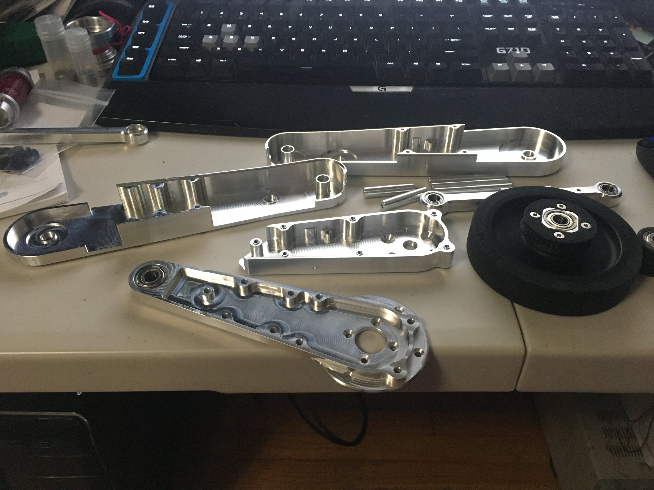
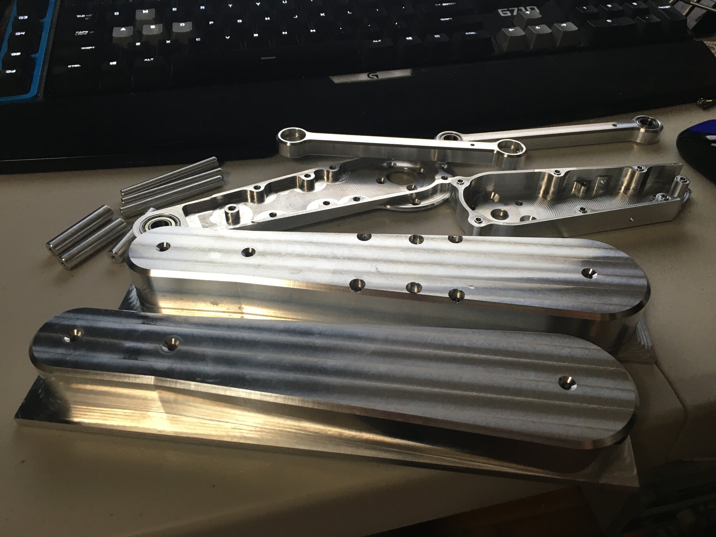
A glorious pile of parts

Next I spent some time making smaller parts like…
Belt tensioners

Motor Controller Mounts/Heatsinks/Covers (took a revision)
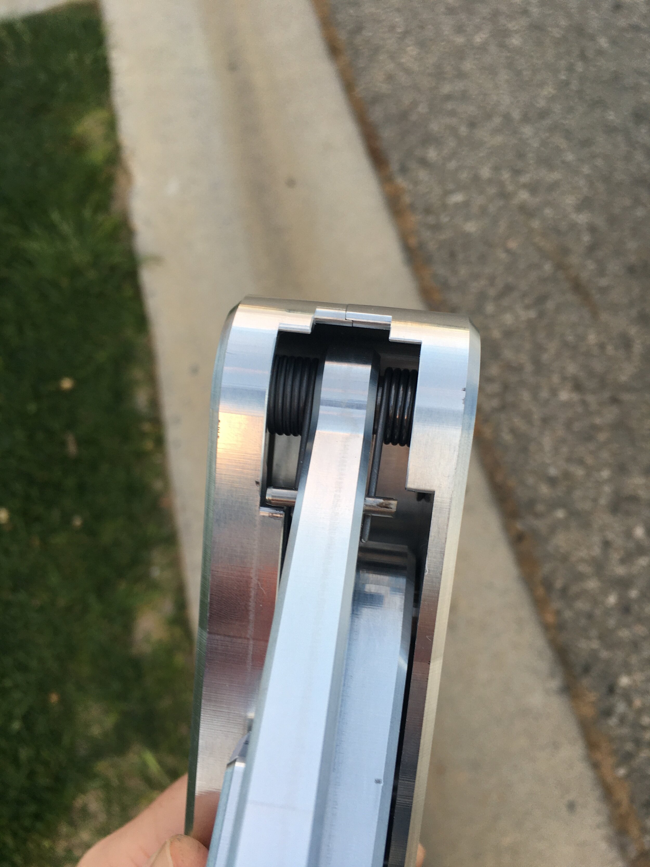
I also installed/tested the torsion springs that help counteract gravity
And now it was time for the body! It was designed to have a rigid skeleton which is just additionally stiffened and mostly covered by the bent sheet metal.
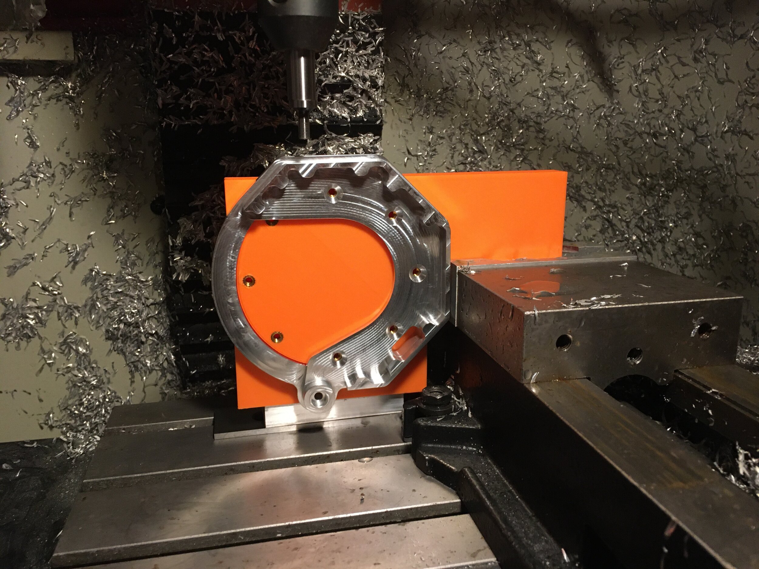
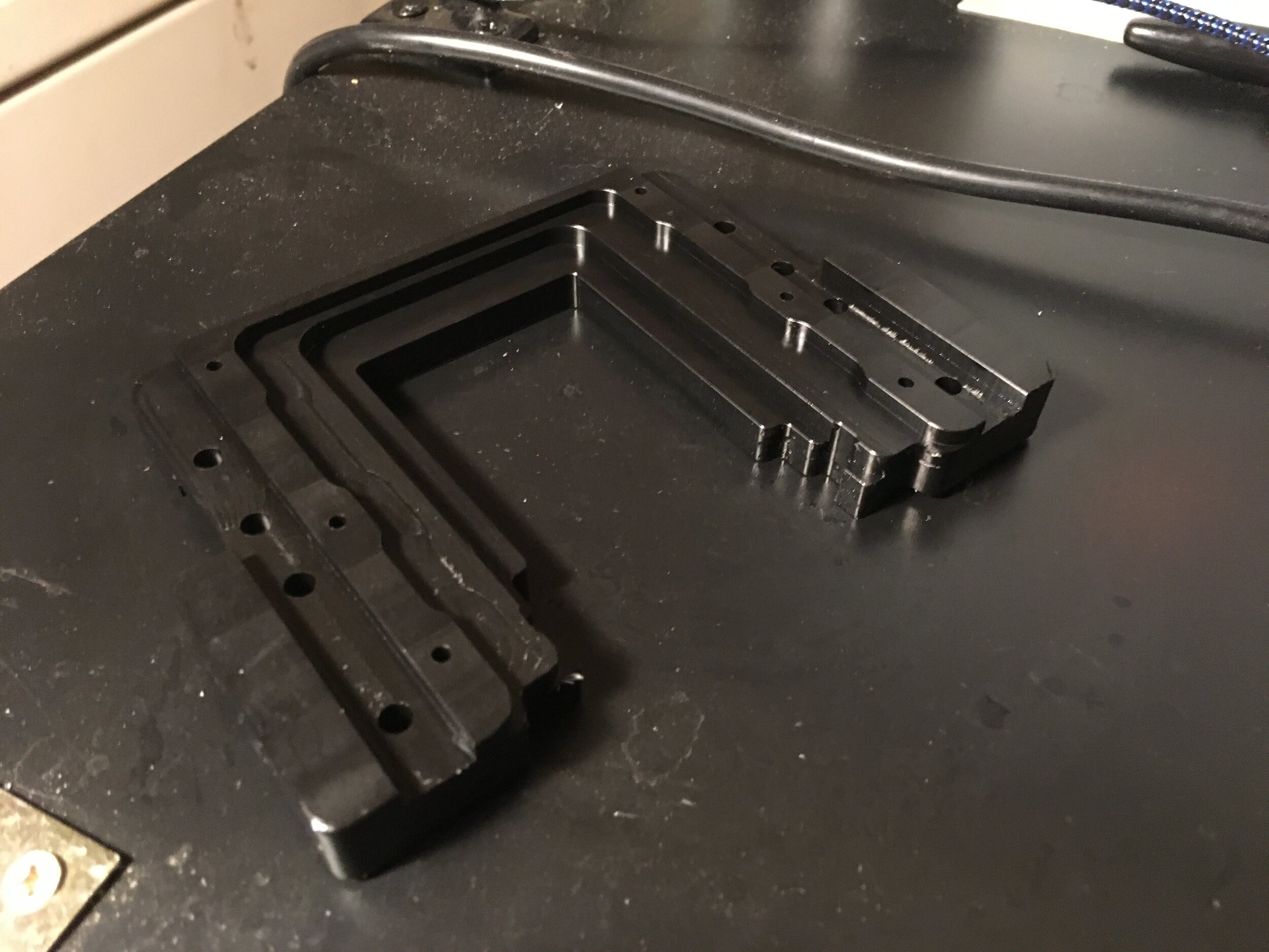
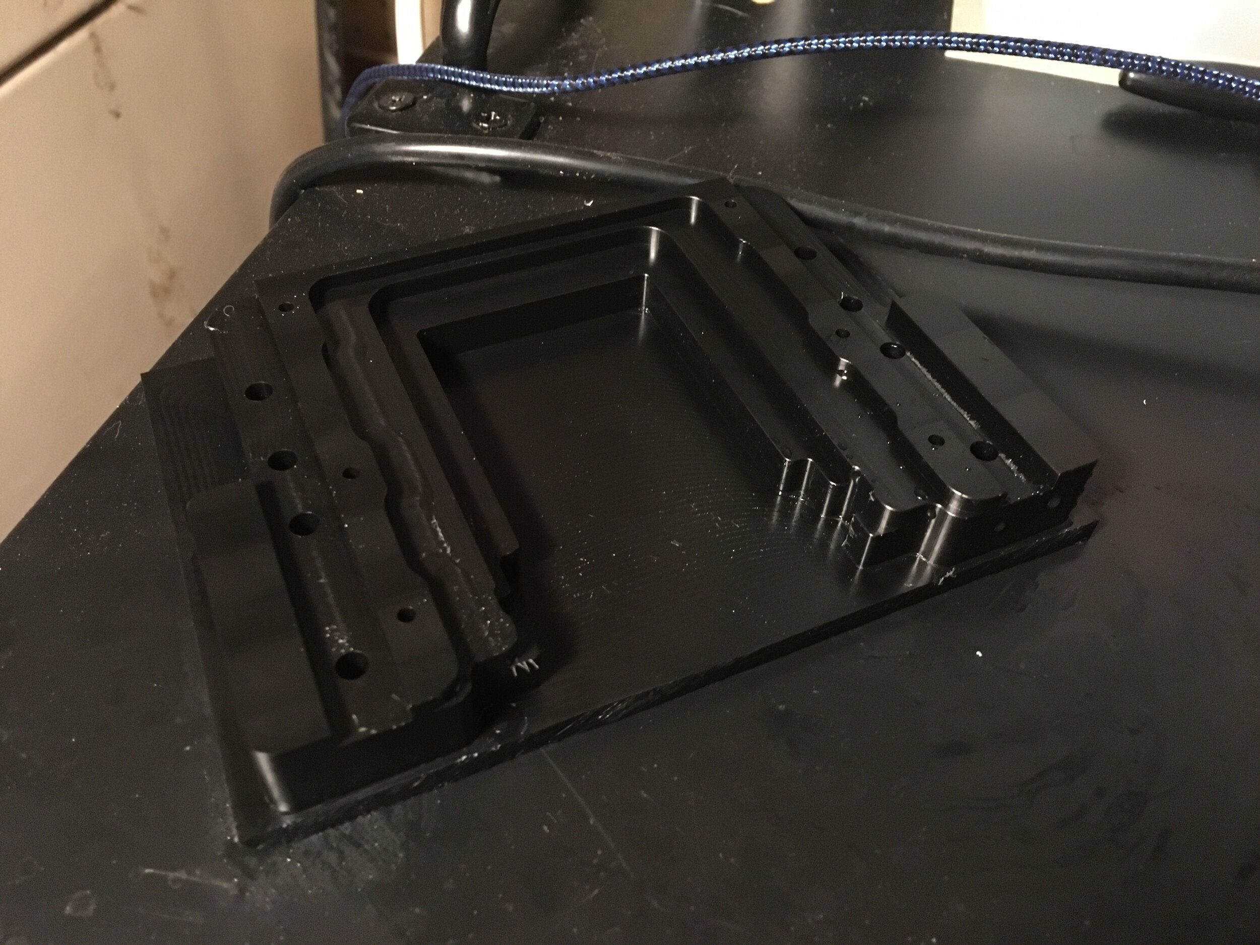
First came the main body pieces which make the 4 bar a 4 bar. These had another tricky feature like the setscrew and I used 3d printing to make a “good enough” fixture.
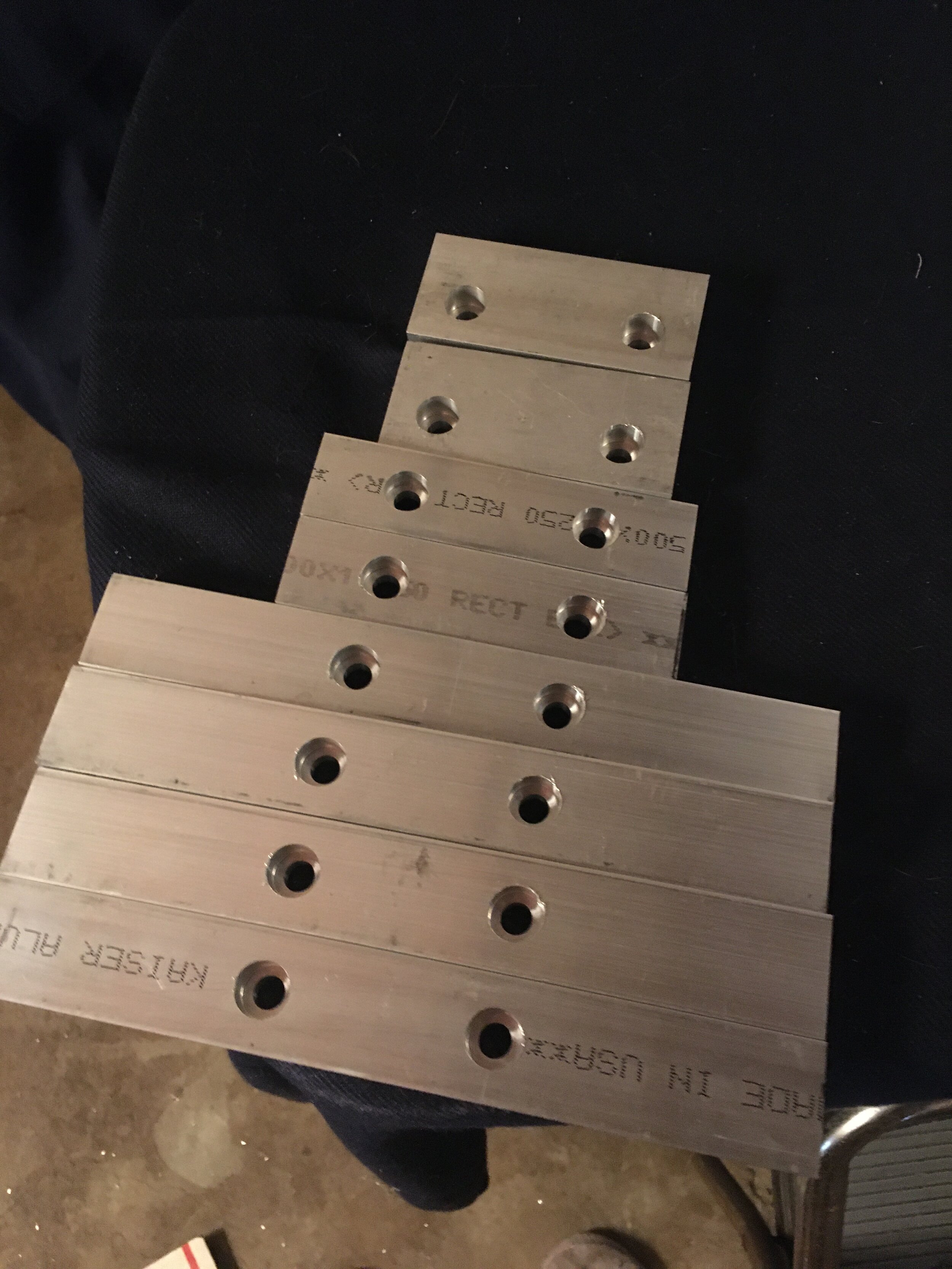
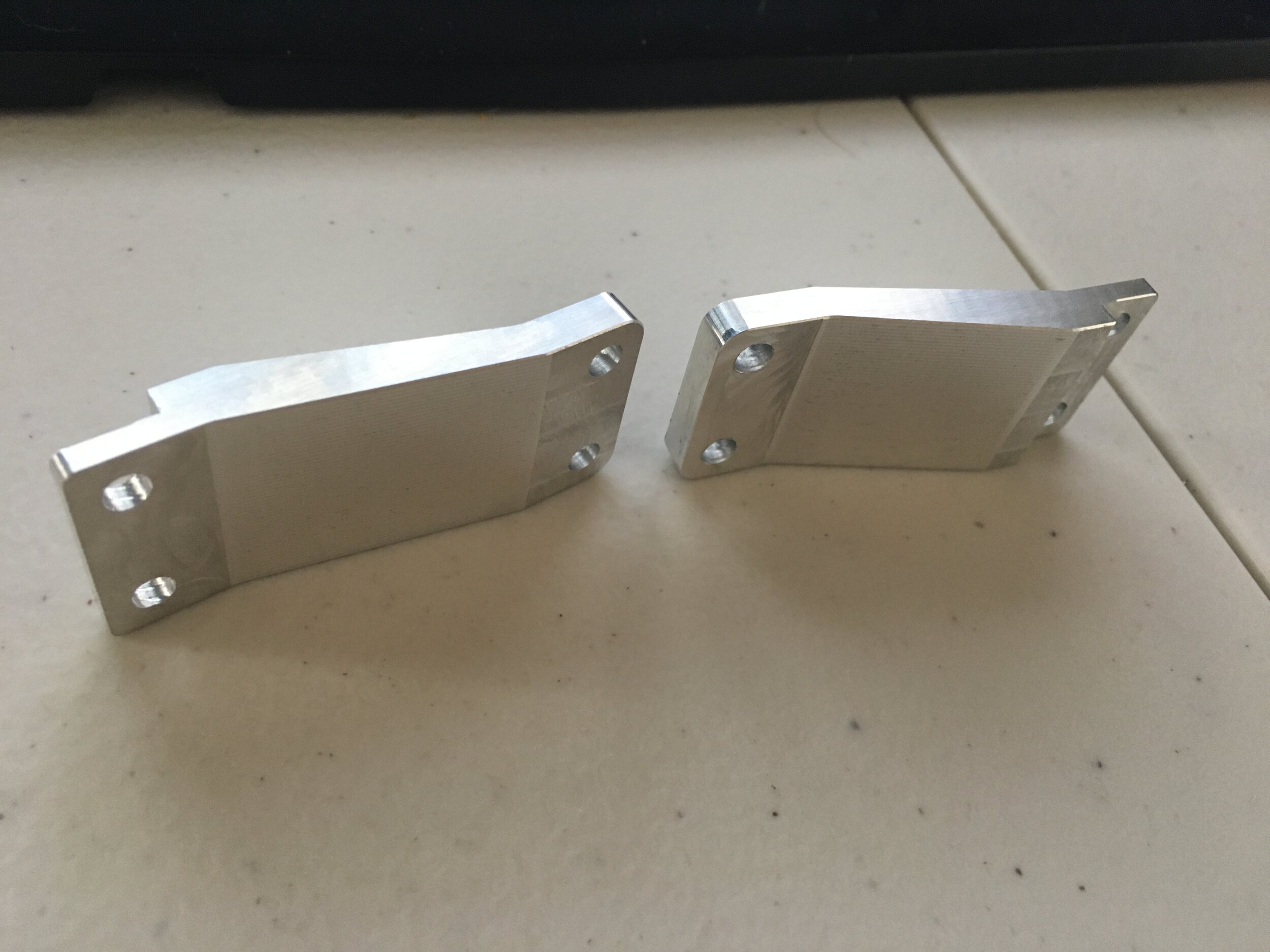
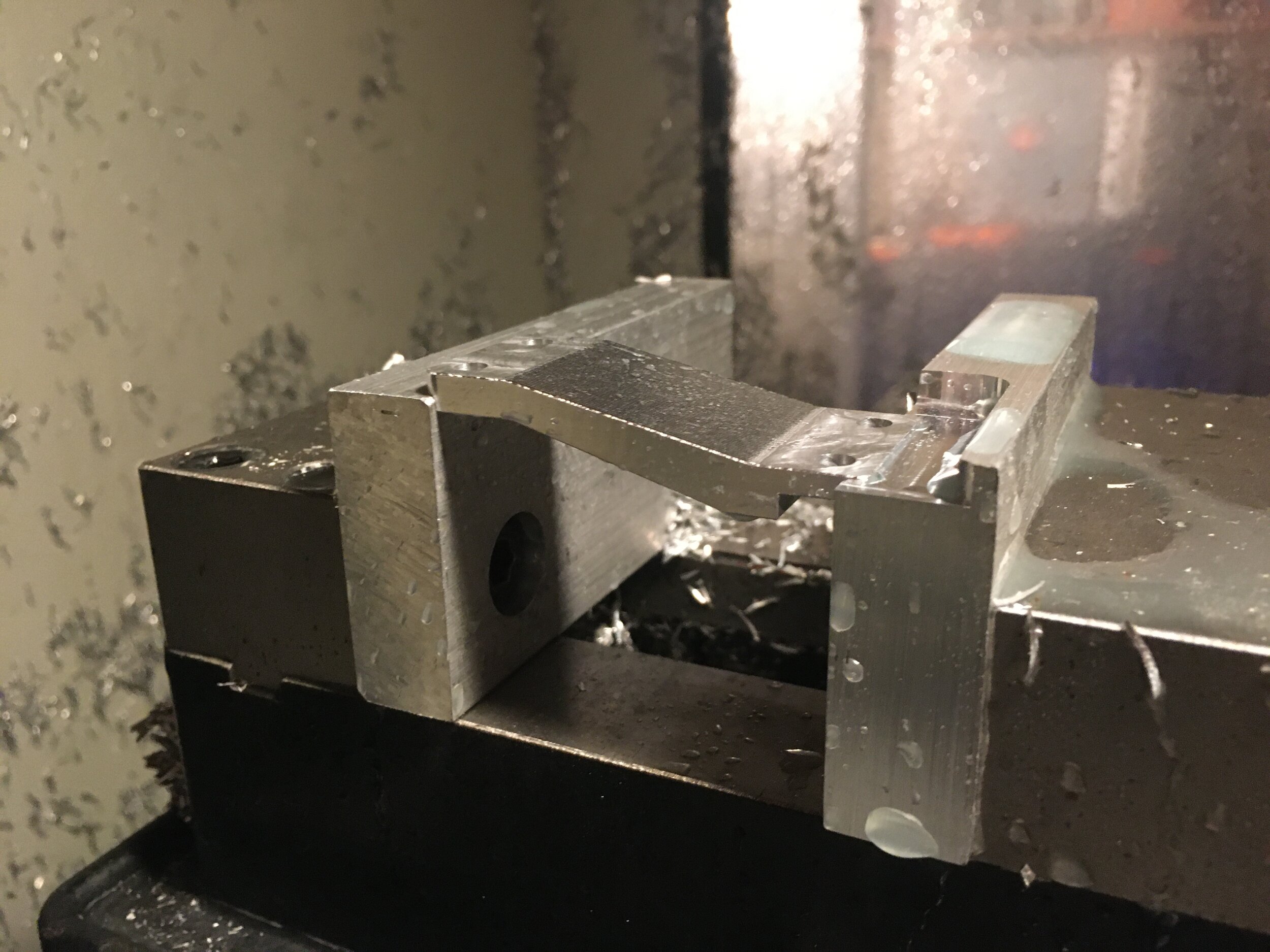
These were the brackets that connect the legs to the battery bracket. Another use of parallel 3d machining
Next came the battery bracket which I made out of delrin for machinability/stiffness vs conductivity purposes
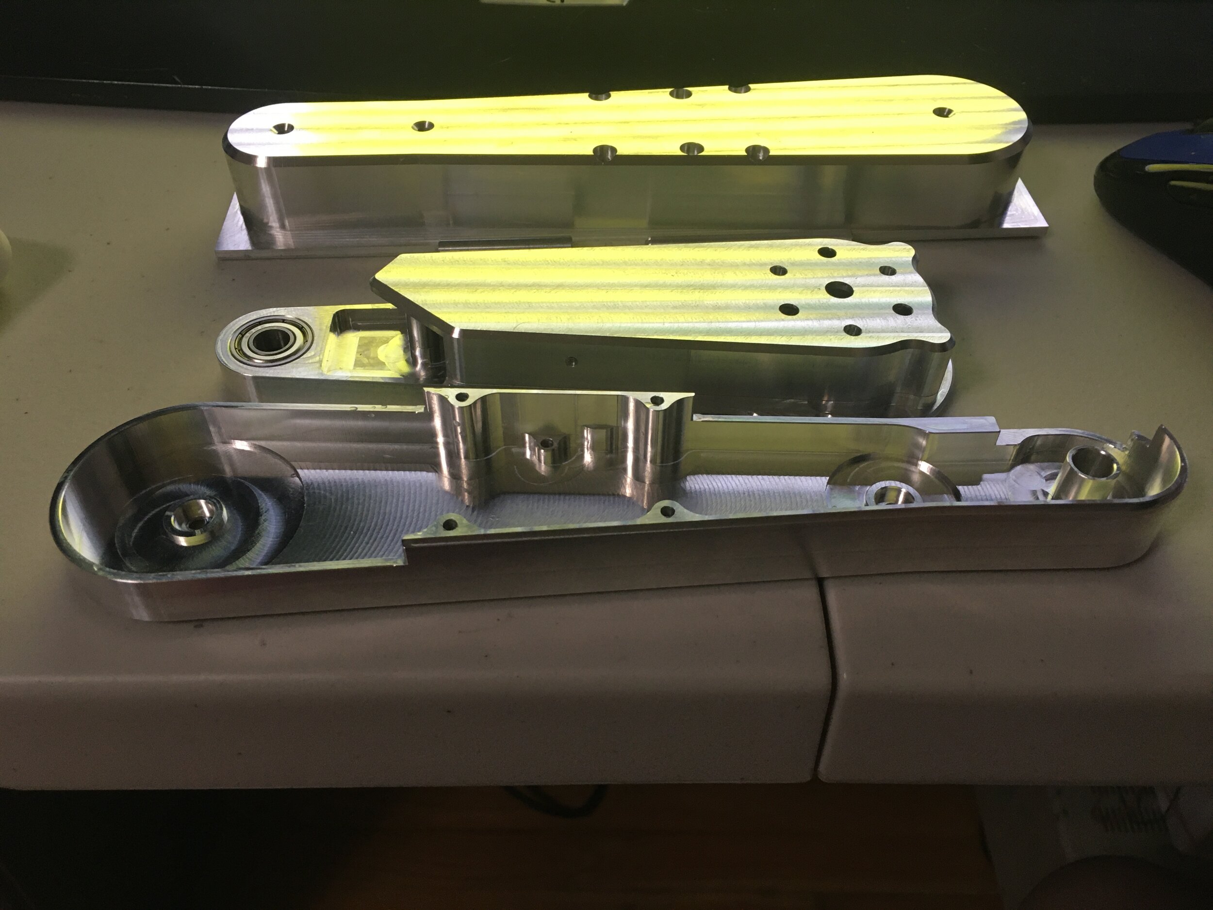
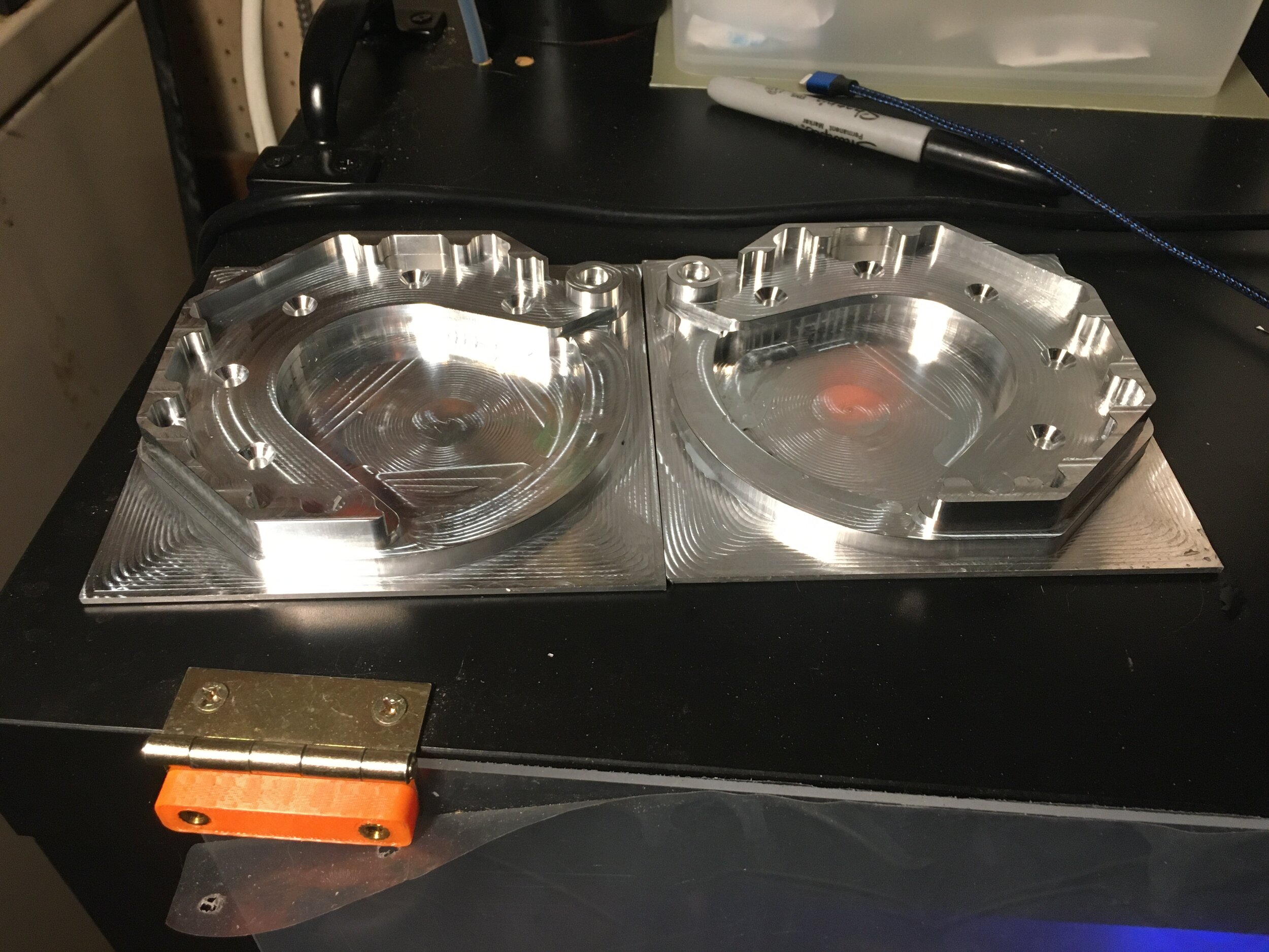
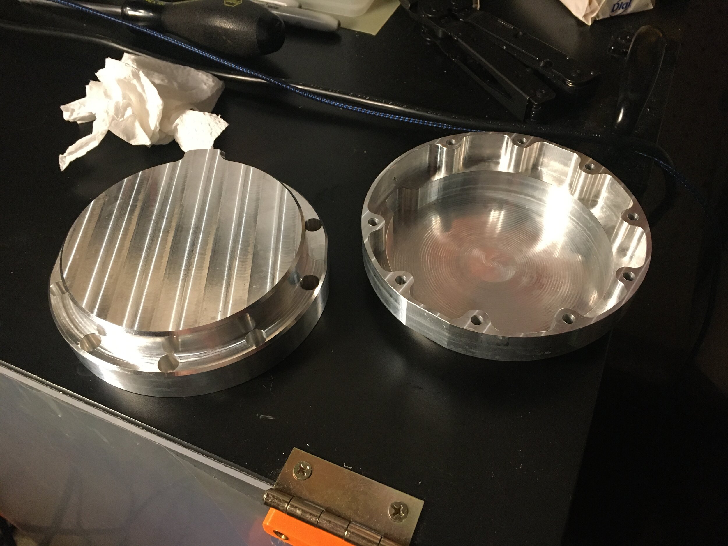
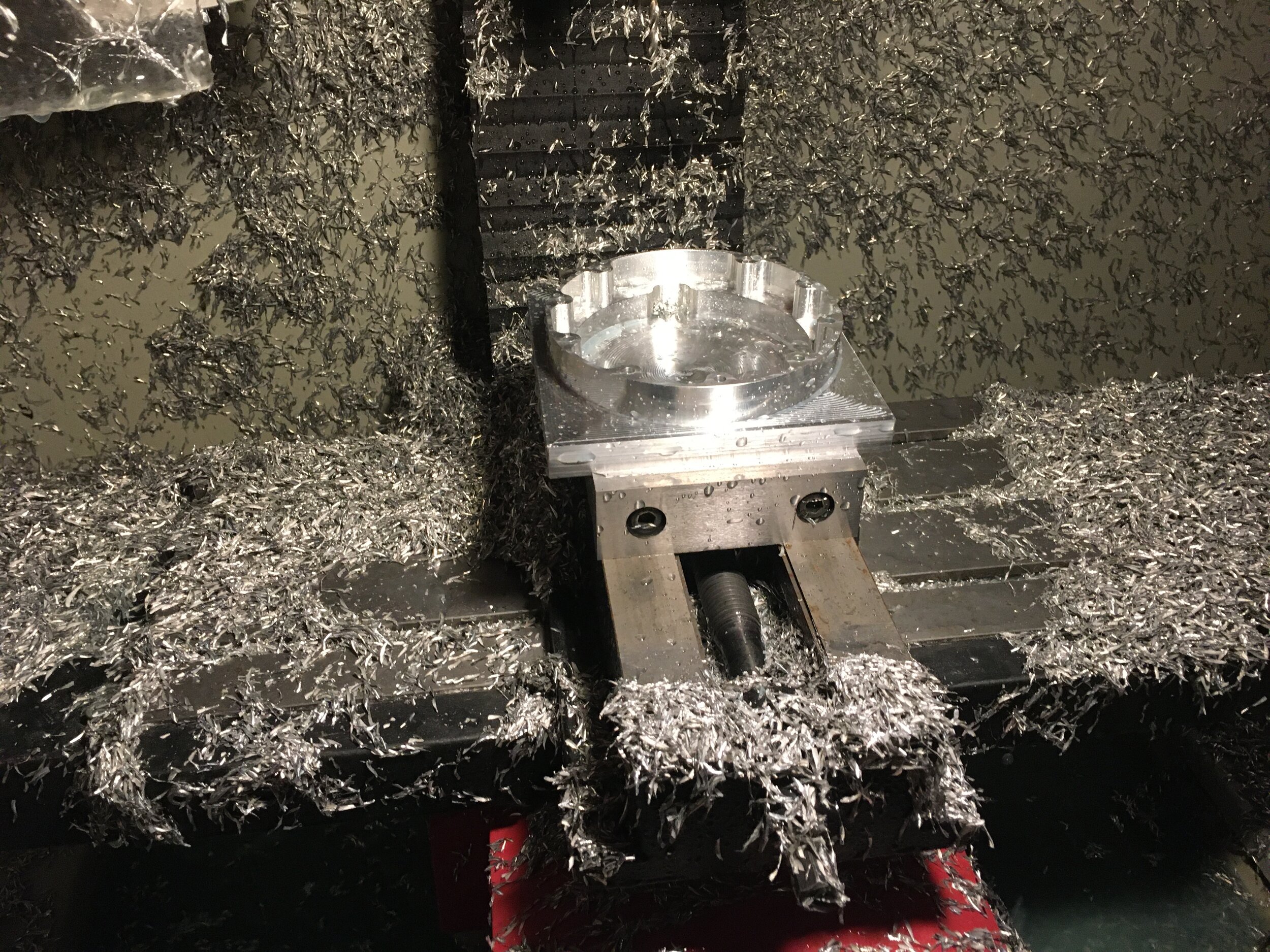
Then the outer covers. These were purely for MRR fun! I hogged these out quickly which was fun. A bit wasteful I’ll admit, but they were pretty cheap ebay billets.
Last came the ribs of the robot
I missed pictures of a couple of the parts like the finished rib, the power switch mount, and the handle but I think everyone gets the gist of how those went given all the other pictures.
And here you can see the naked robot! Although the handle seems excessive at first glance, it adds considerable stiffness to the frame pre-sheet metal

As for the sheet metal parts, I had the 5000 series aluminum cut by SendCutSend for less than $30 total. I always put little notches where the bend lines are so its easy to line up on a manual brake. I used a family friend’s box brake and had an easy time using my digital angle meter. Unfortunately no pics of that process but it was nothing special.
Here’s the finished robot!
The hardware is all working, and I just need to implement the LQR controller I simulated last year. Will make a new post about the firmware and controls later along with a video of the working robot.
Back to work I go!
A picture of the CAD for comparison to real life! Note: most of the chamfers are suppressed on milled parts for CAM reasons
